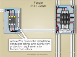
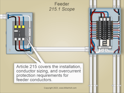
Article 215 covers the installation, conductor sizing, and overcurrent protection requirements for feeder conductors not over 1,000VAC or 1,500VDC (Fig. 1).
Feeders are the conductors between the service disconnect, a separately derived system, or other power supply, and the final branch-circuit OCPD [Art. 100].
Conductor sizing
Feeder conductors must be sized to have an ampacity not less than the largest of the calculations in Sec. 215.2(1) or (2).
(1) Without conductor ampacity correction/adjustment. The ampacity must be at least 125% of the continuous loads, plus 100% of the noncontinuous loads, based on the temperature rating of equipment per Sec. 110.14(C)(1) and Table 310.16, before conductor ampacity correction and/or adjustment.
(2) With conductor ampacity correction/adjustment. The ampacity must be at least 100% of the total load after conductor ampacity correction and/or adjustment per Table 310.15(B)(1)(1) and Table 310.15(C)(1).
Example without conductor ampacity adjustment
Question: What size conductors are required for a 100A continuous load and 100A noncontinuous load where the equipment is rated for 75°C conductors?
(a) 1/0 AWG (b) 2/0 AWG (c) 3/0 AWG (d) 4/0 AWG
Solution:
Step 1: Determine the minimum conductor ampacity.
Minimum Conductor Ampacity = (100A × 125%) + 100A = 225A
Step 2: Determine the conductor size.
4/0 AWG rated 230A at 75°C column [Table 310.16].
Answer: (d) 4/0 AWG
Example with conductor ampacity adjustment
Question: What size conductors rated 90°C are required for four current-carrying conductors supplying a 180A continuous load in an ambient temperature of 100°F, where the equipment is rated for 75°C conductors?
(a) 4/0 AWG (b) 300kcmil (c) 500kcmil (d) 600kcmil
Solution:
Determine the feeder conductor size by the larger of Sec. 215.2(A)(1) or (2) [Sec. 215.2(A)].
Step 1: The circuit conductors must have an ampacity of 180A after conductor ampacity temperature correction [Table 310.15(B)(1)(1)] and adjustment [Table 310.15(C)(1)], based on the conductor’s insulation rating of 90°C. One way to find the conductor size is to determine the conductor ampacity required to supply a 180A continuous load at 100% after correction and adjustment.
Conductor ampacity at 90°C = continuous load at 100% ÷ (correction × adjustment)
Continuous load = 180A
Correction [Table 310.15(B)(1)(1)] = 91% (100°F ambient temperature with 90°C conductor)
Adjustment [Table 310.15(C)(1)] = 80% (four current-carrying conductors)
Conductor ampacity at 90°C Column = 180A ÷ (91% × 80%) = 180A ÷ 73% = 247A
Step 2: Select the conductors from the 90°C column of Table 310.16 [Sec. 110.14(C)(1)(b)(2)].
4/0 AWG THWN-2 is suitable because it has an ampacity of 260A at 90°C before any correction and adjustment.
Determine the feeder conductor size by the larger of Sec. 215.2(A)(1) or (2) [Sec. 215.2(A)]. In this case, based on the conditions specified in this example, 4/0 AWG is the minimum size conductor.
Answer: (a) 4/0 AWG
Note 2: The NEC recommends that feeder conductors be sized to prevent a voltage drop of not more than 3%. It also recommends that the total voltage drop on both feeders and branch circuits not exceed 5%.
Neutral conductor size
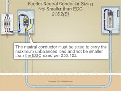
The neutral conductor must be sized to carry the maximum unbalanced load per Sec. 220.61, but must not be smaller than the equipment grounding conductor (EGC) per Sec. 250.122 [Sec. 215.2(B)], as shown in Fig. 2.
Example
Question: What size neutral conductor is required for a feeder consisting of 3/0 AWG phase conductors and one neutral conductor protected by a 200A OCPD when the unbalanced load is 30A and the equipment is rated for 75°C conductor?
(a) 3 AWG (b) 4 AWG (c) 6 AWG (d) 8 AWG
Solution:
Section 220.61 and Table 310.16 permit a 10 AWG neutral conductor rated 30A at 75°C [Sec. 110.14(C)(1) and Table 310.16] to carry the 30A unbalanced load, but must not be smaller than the 6 AWG EGC per Sec. 250.122.
Answer: (c) 6 AWG
Overcurrent protection sizing
Feeder OCPDs must have an ampere rating of not less than 125% of the continuous loads, plus 100% of the noncontinuous loads [Sec. 215.3].
Example
Question: What size feeder overcurrent protection is required for a 100A continuous load and a 100A noncontinuous load?
(a) 200A (b) 225A (c) 250A (d) 300A
Solution:
(100A continuous load × 125% continuous load) + 100A noncontinuous load = 225A [Sec. 240.6(A)]
Answer: (b) 225A
Exception No. 1: Where the assembly, including the OCPDs protecting the feeder(s) is listed for operation at 100% of its rating, the ampere rating of the OCPD can be sized at 100% of the continuous and noncontinuous loads.
Must haves
A feeder must have an equipment grounding conductor [Sec. 215.6].
Each feeder disconnect rated 1,000A or more supplied by a 4-wire, 3-phase, 277V/480V wye-connected system must have ground-fault protection of equipment per Sec. 230.95 and Sec. 240.13 [Sec. 215.10].
Exception No. 2: This Section does not apply if ground fault protection of equipment (GFPE) is provided on the service per Sec. 230.95.
Identification
The feeder neutral conductor must be identified per Sec. 200.6 [Sec. 215.6(A)].
EGCs can be bare, covered, or insulated. Insulated EGCs 6 AWG and smaller must have a continuous outer finish — either green or green with one or more yellow stripes [Sec. 250.119(A)] [Sec. 215.6(B)]
Insulated EGCs 4 AWG and larger can be permanently reidentified with green marking at the time of installation, where accessible [Sec. 250.119(B)].
Where premises wiring is supplied from more than one nominal voltage system, phase conductors must be identified by phase or line, and by system at termination, connection, and splice points [Sec. 215.12(C)(1)].
Identification of the phase conductors can be by color coding, marking tape, tagging, or other means approved by the authority having jurisdiction. The method of identification must be readily available or permanently posted at each branch-circuit panelboard. It must be sufficiently durable to withstand the environment involved, and not be handwritten.
When a premises has more than one voltage system supplying branch circuits, the phase conductors must be identified by phase and system. This can be done by permanently posting an identification legend that describes the method used, such as color-coded marking tape or color-coded insulation.
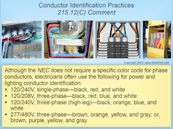
The NEC does not require a specific color code for phase conductors. Whatever color scheme is used, make it consistent wherever phase conductors are terminated or accessible throughout the entire premises. This is especially important when identifying different system voltages and neutrals (Fig. 3).
Barriers must be placed such that no energized phase busbar or terminal is exposed in equipment supplied by:
- A feeder tap [Sec. 240.21(B)] when the OCPD into which the feeder taps terminate is in the open position [Sec. 215.15].
- Transformer secondary conductors [Sec. 240.21(C)] when the OCPD into which the secondary conductors terminate is in the open position [Sec. 215.15].
Surge protection
Where a feeder supplies any of the following occupancies, a surge-protective device (SPD) must be provided:
(1) Dwelling units.
(2) Dormitory units.
(3) Guest rooms and guest suites of hotels and motels.
(4) Areas of nursing homes and limited care facilities used exclusively as patient sleeping rooms [Sec. 215.18].
The SPD must be installed in or adjacent to distribution equipment that contains the branch-circuit OCPD(s).
Surge protection is most effective when closest to the branch circuit. Surges can be generated from multiple sources, including lightning, the electric utility, or utilization equipment.
The SPD must be either Type 1 or Type 2. The distribution SPDs must have a nominal discharge current rating (In) of at least 10kA.
Where the distribution equipment supplied by the feeder is replaced, all the requirements of Sec. 215.18 apply.
Avoiding confusion
Feeders have specific requirements that differ from those of branch circuits. You can think of them as being the main arteries in a city street layout, as opposed to side streets. They handle more traffic at higher speeds and thus are designed and built differently.
As with main arteries, feeders also have destinations other than side streets. For example, a fire pump is supplied by a feeder, not a branch circuit. So, how do you tell these circuits apart? The origin of a feeder is a service disconnect, a separately derived system, or other power supply. The origin of a branch circuit is a panel supplied by a feeder.
About the Author

Mike Holt
Mike Holt is the owner of Mike Holt Enterprises (www.MikeHolt.com), one of the largest electrical publishers in the United States. He earned a master's degree in the Business Administration Program (MBA) from the University of Miami. He earned his reputation as a National Electrical Code (NEC) expert by working his way up through the electrical trade. Formally a construction editor for two different trade publications, Mike started his career as an apprentice electrician and eventually became a master electrician, an electrical inspector, a contractor, and an educator. Mike has taught more than 1,000 classes on 30 different electrical-related subjects — ranging from alarm installations to exam preparation and voltage drop calculations. He continues to produce seminars, videos, books, and online training for the trade as well as contribute monthly Code content to EC&M magazine.


