Article 110 contains general rules that apply to all installations. The rules cover examination, approval, installation, use, and access to spaces around electrical equipment.
Approval
The authority having jurisdiction must approve all electrical conductors and equipment [Sec. 110.2]. Nine considerations for judging equipment are enumerated in Sec. 110.3(A)(1) through (9). For example, the equipment must be suitable for installation and use. Equipment that is listed, labeled, or identified must be installed per manufacturer’s instructions [Sec. 110.3(B)].
Conductor material and sizes
Conductors must be copper, aluminum, or copper-clad aluminum unless otherwise provided in the Code. If the conductor material is not specified in a rule, the sizes in the NEC are based on a copper conductor [Sec. 110. 5]. Conductor sizes are expressed in American Wire Gauge (AWG) or circular mils (cmil) [Sec. 110.6].
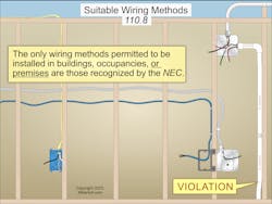
The only wiring methods you can install are those recognized by the NEC [Sec. 110.8], as shown in Fig. 1.
Interrupting and short-circuit ratings
Circuit breakers and fuses must have an interrupting rating of at least the available fault current at the line terminals of the equipment [Sec. 110.9].
Electrical equipment must have a short-circuit current rating that permits the circuit protective device to clear a short circuit or ground fault without extensive damage to the equipment. Listed equipment applied per its listing meets this requirement [Sec. 110.10].
Sections 110.9 and 110.10 use apparently similar terms. Be careful not to confuse “interrupting rating” with “short-circuit rating.”
Available fault current is the largest amount of short-circuit or ground-fault current available at a given point in the electrical system. It is first determined at the secondary terminals of the serving electric utility transformer (by the utility’s engineer). After that, it is calculated at the terminals of the service disconnect. Then panelboards and other equipment as connections “move downstream” from the service. The available fault current decreases at each connection point as you progress away from the service. As the circuit impedance increases, the available fault current decreases.
Factors that affect the available fault current at the utility transformers are system voltage, transformer kVA rating, and impedance. Properties that affect circuit impedance include conductor material (copper versus aluminum), conductor size, conductor length, raceway type (metallic versus nonmetallic), ambient temperature, and motor loads.
Mechanical execution of work
Electrical equipment must be installed in a professional and skillful manner [Sec. 110.12]. For information on accepted industry practices, see ANSI/NECA 1, Standard for Good Workmanship in Electrical Construction.
This rule is one of the most subjective of the Code, but a few things are explicitly addressed in Art. 110, such as closing unused openings [Sec. 110.12(A)] and securely mounting equipment [Sec. 110.13(A)].
Termination and splicing devices
Conductor terminal and splicing devices must be identified for the conductor material, properly installed, and used per the manufacturer’s instructions [Sec. 110.14]. Many common practices, such as using more than one conductor per terminal, are actually Code violations (in this case, unless the terminal is marked for use with more than one conductor).
Take the time to understand the manufacturer’s instructions rather than assume you have been shown the correct way to use a particular terminal or splicing device. Be sure to understand and apply the Sec. 110.14 requirements. These include such things as temperature limitations and terminal connection torque (tighter isn’t necessarily better), which are both common areas for Code violations.
Arc-flash hazard warning label
In other than dwelling units, a label must be on switchboards, switchgear, enclosed panelboards, industrial control panels, meter socket enclosures, and motor control centers to warn qualified persons of the danger associated with an arc flash resulting from a short circuit or ground fault [Sec. 110.16(A)]. The arc-flash hazard warning label must be permanently affixed, have sufficient durability to withstand the environment [Sec. 110.21(B)], and be clearly visible to qualified persons before they examine or service the equipment.
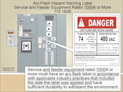
In other than dwelling units, service and feeder equipment rated 1,000A or more must have an arc-flash label with sufficient durability to withstand the environment (Fig. 2).
The arc-flash label is not required in dwelling units because the nominal voltage is single-phase, 120V line-to-ground (240V line-to-line), so the arc fault will self-extinguish with every zero crossing of the sinusoidal waveform. A 3-phase arc fault is sustainable per IEEE-1584.
Maintenance
Equipment servicing and maintenance must comply with the requirements of Sec. 110.17. For example, it must be performed by a qualified person.
Markings
All markings must be of sufficient durability to withstand the environment.
Where caution, warning, or danger hazard markings are required, they must meet the requirements of Sec. 110.21(A). For example, they cannot be handwritten.
Each disconnect must be legibly marked to indicate its purpose unless located and arranged so the purpose is evident [Sec. 110.22(A)]. In other than one- or two-family dwelling units, the disconnect marking must include the identification and location of the circuit source that supplies the disconnect unless located and arranged so the identification and location are evident.
In other than dwelling units, service disconnects must be field marked with the available fault current and the date the fault current calculation was performed [Sec. 110.24(A)]. The available fault current calculation must be documented and available to those who are authorized to design, install, inspect, maintain, or operate the system.
When modifications to the electrical installation affect the available fault current at the service disconnect, the available fault current must be recalculated to ensure the short-circuit current ratings at the service disconnect are sufficient for the available fault current. The required field marking(s) in Sec. 110.24(A) must be adjusted to reflect the new level of available fault current [Sec. 110.24(B)].
Spaces around electrical equipment
This is a commonly misunderstood topic, especially by non-electrical people who make floor space utilization decisions. Since the OSHA tables and working space requirements in 10CFR 1926 Subpart K – Electrical (specifically 1926.403) are copied from Sec. 110.26, you have the force of federal law behind you when insisting these spaces be maintained.
These are minimum spaces, not “desired if you can get it.” Why might a space given in a table not be enough? OSHA and the Code say the space must be maintained “… to permit ready and safe operation and maintenance of such equipment.” That phrase is the guiding principle, not the idea that you’re good if you’re “only an inch” shy of meeting the table value.
This space cannot be used for storage; it is working space [Sec. 110.26(B)].
Depth, width, and height all have requirements [Sec. 110.26(A)(1), (2), (3)]. Table 110.26(A)(1) provides the minimum clear distance, depending upon the nominal voltage to ground and how much exposure there is to live parts.
Access and egress requirements must also be adhered to [Sec. 110.26(C)] with the effects of open equipment doors being considered [Sec. 110.26].
Other equipment, such as raceways, cables, wireways, transformers, or support structures, cannot extend more than 6 in. into the working space in front of the electrical equipment. There are three Exceptions to this rule (e.g., Ex 3: Meters can be installed in the required working space).
If equipment likely to require examination, adjustment, servicing, or maintenance while energized is above a suspended ceiling or in a crawl space, all six conditions of Sec. 110.26(A)(4) apply. For example, the working space must permit equipment doors to open 90 degrees.
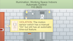
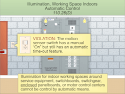
Having sufficient space doesn’t do much good if you can’t see what you are doing. Thus, illumination is required for working spaces about service equipment, switchboards, switchgear, enclosed panelboards, or motor control centers installed indoors [Sec. 110.26(D)]. It cannot be controlled by automatic means (Fig. 3).
Service equipment, switchboards, panelboards, and motor control centers must have dedicated electrical equipment space and be protected from damage that could result from condensation, leaks, breaks in the foreign systems, or vehicular traffic [Sec. 110.26(E)]. No piping, ducts, or other equipment foreign to the electrical system can be installed in this dedicated electrical equipment space.
Outdoor installations for service equipment, switchboards, panelboards, and motor control centers must comply with the requirements of Sec. 110.26(E)(2).
For example, it must be protected from vehicular traffic.
General conclusions
For electrical professionals wishing to become proficient in the Code, Art. 110 is the second best place to start because it applies to all installations. The first is Art. 100, so that you can understand the terms used in all of the other Articles that follow.
About the Author

Mike Holt
Mike Holt is the owner of Mike Holt Enterprises (www.MikeHolt.com), one of the largest electrical publishers in the United States. He earned a master's degree in the Business Administration Program (MBA) from the University of Miami. He earned his reputation as a National Electrical Code (NEC) expert by working his way up through the electrical trade. Formally a construction editor for two different trade publications, Mike started his career as an apprentice electrician and eventually became a master electrician, an electrical inspector, a contractor, and an educator. Mike has taught more than 1,000 classes on 30 different electrical-related subjects — ranging from alarm installations to exam preparation and voltage drop calculations. He continues to produce seminars, videos, books, and online training for the trade as well as contribute monthly Code content to EC&M magazine.


