Grounding and Bonding Performance: NEC Requirements
Electricity does not choose “the path of least resistance,” but flows on all paths presented to it. The flow divides among those paths in inverse proportion to their impedances (those paths with lower impedance get proportionately more of the current). This fundamental concept of circuit design is described in Kirchhoff’s law of parallel circuits. Understanding this is the key to understanding bonding and grounding.
Though related and working together to form a protective system, grounding and bonding serve two completely different purposes. Here are two simplified definitions that are very important:
- Grounding is a connection to the earth. The earth cannot serve as a bonding jumper, due to its impedance. But it is a great “sink” for high-voltage transients such as those from lightning.
- Bonding is a metallic, low-impedance path between metallic objects. It puts metal parts at the same potential, thus eliminating a dangerous flow of current between them.
Limiting induced voltage
We connect electrical systems to the earth (ground) to limit induced voltage on the system windings and system conductors from indirect lightning strikes (those that are not a direct hit) [Sec. 250.4(A)(1)]. System grounding extends insulation life for motors, transformers, and other loads.
For this to work, you must make the grounding electrode conductor and grounding electrode bonding jumpers no longer than necessary and avoid unnecessary bends and loops. Because it is both high-frequency and high-voltage, lightning can jump from those bends and loops to nearby objects instead of staying in the conductor. This jump is called a “side flash” and could cause a fire hazard if it occurs around combustible materials (such as wood).
Metal parts of electrical equipment must be grounded (connected to the earth) to limit lightning-induced voltage to ground on the metal parts of equipment [Sec. 250.4(A)(2)]. Where do you ground this equipment? The thing is, you don’t ground it directly. You bond it all to the equipment grounding conductor (EGC), and then you ground the EGC at services [Sec. 250.24(A)], transformers [Sec. 250.30(A)], and separate buildings supplied by a feeder [Sec. 250.32(A)].
Failure to ground (connect to the earth) the EGC can result in millions of volts of induced voltage on the metal parts if there’s a nearby indirect lightning strike. This energy seeks a path to the earth within the building—possibly resulting in a fire and/or electric shock from a side flash.
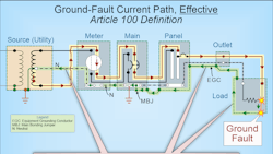
Establishing an effective ground-fault current path
An “effective ground-fault current path” is an intentionally constructed low-impedance conductive path designed to carry fault current from the point of a ground fault to the source. It has two purposes:
- To open the circuit overcurrent protective device (OCPD) [Art. 100], as shown in Fig. 1.
- To quickly remove dangerous voltage on metal parts from a ground fault.
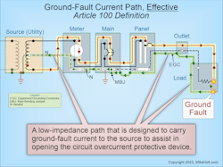
The effective ground-fault current path must have sufficiently low impedance to the source so fault current will quickly rise to a level that will open the circuit OCPD. That means it has to be metal. When we use metal to create this path, we call that bonding.
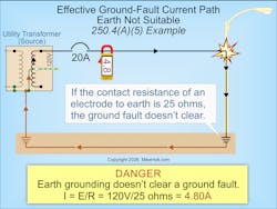
The earth cannot serve as an effective ground-fault current path. Trying to use the earth as an effective ground-fault current path does not remove dangerous differences in potential because the fault return path impedance is so high that very little fault current returns to the source. As a result, the circuit OCPD will not open, and metal parts associated with the electrical installation, metal piping, and structural building steel will become — and remain — energized.
The time it takes for an OCPD to open depends on the magnitude of the fault current. A higher fault current value will result in a shorter clearing time for the OCPD. This principle is called “inverse time.” For example, a 20A OCPD with an overload of 40A (two times the 20A rating) takes 25 to 150 seconds to open. That same device at 100A (five times the 20A rating) trips in 5 to 20 seconds.
Metal raceways, cables, and enclosures that could become energized must be installed in a manner that creates a low-impedance circuit to facilitate the opening of the OCPD [Sec. 250.4(A)(5)]. And these, along with conductive materials such as metal piping systems and exposed structural steel, must be connected and bonded to the source to establish an effective ground-fault current path [Sec. 250.4(A)(3) and (4)].
Let’s answer a question to tie together what we just covered. What will the maximum fault current be when there is a 120V ground fault to the metal parts of a light pole that is grounded to a 25Ω ground rod, but not bonded to an effective ground-fault current path (Fig. 2)?
(a) 3.70A
(b) 4.80A
(c) 5.20A
(d) 6.40A
Solution:
I = Volts ÷ Resistance
I = 120V ÷ 25Ω
I = 4.80A
Answer: (b) 4.80A
High-performance grounding
If you understand earth shells, you will have an easier time applying the requirements for the grounding electrode system and the grounding electrode conductor. You will find these requirements in Art. 250, Part III.
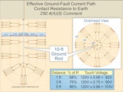
According to ANSI/IEEE 142, Recommended Practice for Grounding of Industrial and Commercial Power Systems (Green Book) [4.1.1], the resistance of the soil outward from a 10-ft ground rod is equal to the sum of the series resistances of the earth shells. The shell nearest the ground rod has the highest resistance, and each shell farther out has progressively larger area and lower resistance.
The earth is an excellent conductor due to an almost limitless number of parallel paths over which electrons can flow. However, the problem lies in the contact resistance between the grounding electrode and the earth. The surface area of the electrode contacting the earth is minimal compared to the earth itself.
Since voltage is directly proportional to resistance (Ohm’s Law), the voltage gradient of the earth around an energized ground rod (assuming a 120V ground fault) will be as shown in Fig. 3.
High-performance bonding
Remember, the low impedance of the metallic pathway is what makes bonding work. So you want to keep it low at each connection, and you want to provide parallel bonding paths where practical. The mechanical integrity of the bonding jumper system is also paramount. Selecting the correct connectors for the application and ensuring they are used correctly (e.g., proper torquing values and techniques) are two keys to ensuring low impedance and high mechanical integrity.
As you bond metallic objects together, you are building part of the EGC. Given its construction requirements and its primary function, the EGC serves more the purpose of bonding than grounding. However, it does ultimately connect to the grounding point at the service or separately derived system.
Section 250.118(A) lists 14 types of things you can use as an EGC. Grounding electrode conductors are specifically prohibited for this use [Sec. 250.118(B)]. These 14 types include metallic raceways, cables, and gutters. While you certainly can run a conductor inside a raceway to provide the EGC, the advantage of using the raceway is that its larger surface area takes advantage of the skin effect to provide a better path for high-frequency undesired current.
For high-performance bonding, use both the enclosed conductor [Sec. 250.118(A)(1)] and the metal raceway. Then look at additional ways to exceed the NEC bonding requirements, for example, by adding bonding jumpers across raceway couplings (as is commonly done in data centers).
Ground or bond?
To avoid grounding when you should be bonding, remember that you bond if the equipment is on the load side of the service or separately derived source. If a facility is having power quality problems and you spot a motor with a ground rod connection instead of an EGC connection, you have found one cause (perhaps the cause). Follow the requirements of Art. 250, Parts V, VI, and VII to prevent or clear up these kinds of problems.
On the other hand, a service or separately derived source that doesn’t meet the grounding requirements of Art. 250, Parts II and III are going to be vulnerable to high-voltage transients, and so will the connected loads.
About the Author

Mike Holt
Mike Holt is the owner of Mike Holt Enterprises (www.MikeHolt.com), one of the largest electrical publishers in the United States. He earned a master's degree in the Business Administration Program (MBA) from the University of Miami. He earned his reputation as a National Electrical Code (NEC) expert by working his way up through the electrical trade. Formally a construction editor for two different trade publications, Mike started his career as an apprentice electrician and eventually became a master electrician, an electrical inspector, a contractor, and an educator. Mike has taught more than 1,000 classes on 30 different electrical-related subjects — ranging from alarm installations to exam preparation and voltage drop calculations. He continues to produce seminars, videos, books, and online training for the trade as well as contribute monthly Code content to EC&M magazine.