Key Highlights
- The neutral conductor is typically the grounded conductor connected to the system's neutral point, carrying current under normal operation.
- Grounding electrode conductors must be connected at accessible points from the load end of service conductors, with specific rules for outdoor transformers and dual-fed services.
- Load side neutral connections to metal parts or equipment grounding conductors are prohibited to prevent dangerous neutral currents on conductive surfaces.
- The main bonding jumper bonds the neutral conductor to the equipment grounding conductor, enabling proper operation of overcurrent protective devices.
- Neutral conductors must be properly sized based on the load and installation method, with specific requirements for conductors in parallel or multiple raceways.
The grounded conductor is typically the neutral, so going forward, we will refer to the grounded conductor as the neutral. The Art. 100 definition for “neutral” conductor was added in the 2008 NEC. It’s the conductor connected to the neutral point (also defined in Art. 100) of a system that is intended to carry current under normal conditions. If you have a 2-wire system or a corner grounded delta system, the grounded conductor would not be a neutral.
The service neutral conductor provides the effective ground-fault current path to the source to remove dangerous voltage from a ground fault by opening the circuit overcurrent protective device (OCPD) [Sec. 250.4(A)(3) and Sec. 250.4(A)(5)].
Grounding electrode connection
A premise’s wiring system supplied by a grounded service must have a grounding electrode conductor (GEC) connected to the service neutral conductor per Sec. 250.24(A)(1) through (4):
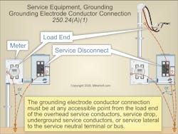
(1) General. The GEC connection to the neutral conductor at service equipment must be made at any accessible point from the load end of the overhead service conductors, service drop, underground service conductors, or service lateral to the terminal or bus to which the service neutral conductor is connected at the service disconnect (Fig. 1).
Some inspectors require the GEC connection to the service neutral conductor to be made at the meter socket enclosure, while others insist the connection be made only within the service disconnect. Grounding at either location complies with this rule, but be sure you know the local utility company’s policy on connections inside the meter socket.
(2) Outdoor transformer. If the service supply transformer is outside, you must make at least one additional grounding connection from the neutral conductor to a grounding electrode.
(3) Dual-fed services. For these, you may use a single GEC connection to the tie point of the neutral conductor(s) from each power source.
(4) Service equipment, main bonding jumper. If the main bonding jumper specified in Sec. 250.28 is a wire or busbar, you can terminate the GEC to the equipment grounding terminal, bar, or bus to which the main bonding jumper is connected, instead of to the neutral terminal.
Load side connections
A neutral conductor cannot be connected to metal parts of equipment or the equipment grounding conductor (EGC) on the load side of the service disconnect [Sec. 250.24(B)].
If a neutral-to-case connection is made on the load side of the service disconnect, objectionable neutral current will flow on conductive metal parts of electrical equipment [Sec. 250.6(A)]. Objectionable neutral current on metal parts of electrical equipment can be extremely dangerous. It does not take much current to cause electric shock or death (from ventricular fibrillation) and a fire.
Main bonding jumper
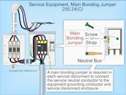
A “main bonding jumper” is a wire, screw, or busbar used to connect the service neutral conductor to the EGC, supply-side bonding jumper, or both at the service disconnect enclosure [Art. 100].
The main bonding jumper is a vital component of bonding. It facilitates the operation of overcurrent protective devices and is a critical part of the grounding system, since it bonds the neutral conductor, service enclosure, and the EGC to the GEC via the grounding electrode conductor.
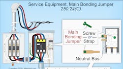
A main bonding jumper is required to bond the EGC to the neutral conductor in each service disconnect enclosure per Sec. 250.28 [Sec. 250.24(C)], as shown in Fig. 2.
Service neutral conductor requirements
A service neutral conductor must be:
- Installed and routed with the phase conductors.
- Connected to the neutral terminal or bus at each service disconnect enclosure, regardless of whether line-to-neutral loads are supplied [Sec. 250.24(D)].
If the neutral conductor is opened, dangerous voltage may be present on metal parts under normal conditions, providing the potential for electric shock. If the earth’s ground resistance is 25Ω and the load’s resistance is 25Ω, the voltage drop across each of these resistances will be half of the voltage source. Since the neutral is connected to the service disconnect, all metal parts will be elevated 60V above the earth’s voltage for a 120V/240V system.
Dangerous voltage from a ground fault will not be removed from metal parts, metal piping, and structural steel if the service-disconnect enclosure is not connected to the service neutral conductor. This is because the contact resistance of a grounding electrode to the earth is so great that insufficient ground-fault current returns to the source if that is the only ground-fault current return path available to open the circuit OCPD.
The service neutral conductor(s) must be sized per Sec. 250.24(D)(1) and (2):
(1) Sizing for a Single Raceway or Cable. The neutral conductor cannot be smaller than specified in Table 250.102(C)(1) [Sec. 250.24(D)(1)]. The neutral conductor also must have the capacity to carry the maximum unbalanced neutral current per
Sec. 220.61.
Example Question: What is the minimum size copper service neutral conductor required when the service phase conductors are 4/0 AWG?
(a) 3 AWG (b) 2 AWG (c) 1 AWG (d) 1/0 AWG
Solution:
2 AWG [Table 250.102(C)(1)]
Answer: (b) 2 AWG
(2) Neutral Conductors Connected in Parallel in Two or More Raceways or Cables. If service conductors are installed in parallel in two or more raceways or cables, the neutral conductor in each raceway must be sized per
Sec. 250.24(D)(2)(a) or (D)(2)(b).
(a) The neutral conductor in each raceway must be sized per Table 250.102(C)(1), based on the circular mil area of the largest phase conductor in each raceway, but not smaller than 1/0 AWG.
(b) The neutral conductors must be sized based on the sum of the circular mil areas of the largest phase conductors from each set connected in parallel in each raceway per Table 250.102(C)(1).
Note: See Sec. 310.10(G) for neutral conductors connected in parallel.
The grounded conductor of a 3-phase, 3-wire delta service must have an ampacity of at least that of the phase conductors [Sec. 250.24(D)(3)]. The GEC at service equipment must be sized per Sec. 250.66 [Sec. 250.24(E)].
Buildings supplied by a feeder
A building supplied by a feeder must have a GEC connected to a grounding electrode system per Part III of Art. 250 [Sec. 250.32(A)], as shown in Fig. 3.
A building supplied by a feeder must have a GEC connected to a grounding electrode system per Part III of Art. 250 [Sec. 250.32(A)], as shown in Fig. 3.
Exception: A grounding electrode system and GEC is not required for a building if it is supplied by a single branch circuit or multiwire branch circuit.
The metal parts of the building disconnect must be connected to the feeder EGC of a type described in Sec. 250.118(A) [Sec. 250.32(B)(1)]. Where the supply circuit EGC is of the wire type, it must be sized per
Sec. 250.122.
To prevent dangerous objectionable neutral current from flowing on metal parts [Sec. 250.6(A)], you cannot connect the supply circuit neutral conductor to the remote building disconnect metal enclosure. [Sec. 250.142(B)].
Exception 1: The neutral conductor can serve as the ground-fault return path for the building disconnect for existing installations where there are no continuous metallic paths between buildings and structures, ground-fault protection of equipment is not installed on the supply side of the circuit, and the neutral conductor is sized no smaller than the larger of:
(1) The maximum unbalanced calculated neutral load per Sec. 220.61.
(2) The minimum EGC size per Sec. 250.122.
The GEC must terminate to the equipment grounding terminal of the disconnect (not the neutral terminal) and must be sized per Sec. 250.66 [Sec. 250.32(E)].
Example question: What size copper GEC is required for a building disconnect supplied with a 3/0 AWG feeder with a concrete-encased electrode?
(a) 4 AWG (b) 2 AWG (c) 1 AWG (d) 1/0 AWG
Answer: (a) 4 AWG
Note: If the GEC is connected to a concrete-encased electrode(s), the portion of the conductor that connects only to the concrete-encased electrode(s) is not required to be larger than 4 AWG copper [Sec. 250.66(B)].
If the GEC is connected to a rod(s), the portion of the conductor that connects only to the rod(s) is not required to be larger than 6 AWG copper
[Sec. 250.66(A)].
Avoiding mistakes
Don’t confuse the neutral (grounded conductor) with a GEC (one used to extend the ground connection) or a bonding jumper (one that puts metallic objects at zero potential from each other). The neutral carries the unbalanced current, and you don’t want to conduct that current through enclosure bodies or along the outside of raceway.
About the Author

Mike Holt
Mike Holt is the owner of Mike Holt Enterprises (www.MikeHolt.com), one of the largest electrical publishers in the United States. He earned a master's degree in the Business Administration Program (MBA) from the University of Miami. He earned his reputation as a National Electrical Code (NEC) expert by working his way up through the electrical trade. Formally a construction editor for two different trade publications, Mike started his career as an apprentice electrician and eventually became a master electrician, an electrical inspector, a contractor, and an educator. Mike has taught more than 1,000 classes on 30 different electrical-related subjects — ranging from alarm installations to exam preparation and voltage drop calculations. He continues to produce seminars, videos, books, and online training for the trade as well as contribute monthly Code content to EC&M magazine.


