NEC Requirements for Grounding of Separately Derived Systems
Takeaways
- A separately derived system (SDS) has no direct connection to other sources except through grounding and bonding.
- Grounding and bonding must be performed at the source, not on the load side, to prevent potential differences and ensure safety.
- System bonding jumpers connect the secondary neutral to the equipment grounding conductor at specific points, complying with NEC Sec. 250.28 and Sec. 250.102(C).
- Multiple transformer SDSs can share a common grounding electrode conductor, but connections must be accessible and made with approved methods like exothermic welding.

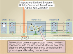
A separately derived system (SDS) is an electrical power supply having no direct connection(s) to the circuit conductors of any other electrical source other than those established by grounding and bonding connections [Art. 100], as shown in Fig. 1.
Except for autotransformers, transformers are separately derived because the primary conductors have no direct electrical connection to the secondary conductors.
Transformer SDSs must be bonded and grounded per Sec. 250.30(A)(1) through (A)(8). On the load side of the bonding jumper, you cannot connect the neutral conductor to:
- The transformer case.
- Metal parts of equipment.
- Equipment grounding conductors.
System bonding jumper
A system bonding jumper is the connection between the neutral conductor (or grounded-phase conductor) and the equipment grounding conductor (EGC), supply-side bonding jumper, or both at a transformer SDS.
A system bonding jumper must be installed at the secondary neutral point or the secondary disconnect neutral terminal (not both). The system bonding jumper must comply with Sec. 250.28 and be sized per Sec. 250.102(C).
The grounding electrode conductor (GEC) must terminate at the point where the system bonding jumper has been installed [Sec. 250.30(A)(5)].
Exception No. 2: If a structure is supplied by a feeder from an outdoor transformer SDS, a system bonding jumper at both the source and the first disconnect is permitted if it does not establish a parallel path for the neutral current. The neutral conductor cannot be smaller than the size specified for the system bonding jumper, and it is not required to be larger than the phase conductor(s).
A system bonding jumper at the source connects the secondary neutral point of the system to the metal enclosure of the transformer SDS [Sec. 250.30(A)(1)(a)]. A system bonding jumper at the first disconnecting means connects the neutral conductor of the transformer secondary to the metal enclosure at the secondary disconnect [Sec. 250.30(A)(1)(b)].
Supply-side bonding jumper
A supply-side bonding jumper installed from the transformer enclosure to the secondary disconnect enclosure can be a non-flexible metal raceway or of the wire type.
The supply-side bonding jumper can be rigid metal conduit (RMC), intermediate metal conduit (IMC), or electrical metallic tubing (EMT) run between the transformer SDS enclosure and the secondary system disconnect enclosure. A nonmetallic or flexible raceway must have a supply-side bonding jumper of the wire type.
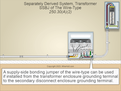
A supply-side bonding jumper of the wire type must be sized per Sec. 250.102(C) based on the size or area of the secondary phase conductors in the raceway or cable (Fig. 2).
System grounded conductor
The system neutral conductor is not required to be larger than the phase conductors [Sec. 250.30(A)(3)]. Oversizing the neutral conductor does not solve excessive unbalanced current returning in the neutral. It is merely a coping strategy that still leaves you with the energy waste and other problems related to reliability issues.
Suppose the system bonding jumper is installed at the secondary system disconnect instead of at the transformer SDS, and the neutral is run in a single raceway. In that case, the neutral must be run from the transformer SDS to the secondary system disconnect. It must be sized per Table 250.102(C)(1) based on the size or area of the secondary phase conductor.
What if you run that neutral paralleled in two or more raceways or cables? In that case, you size the neutral conductor(s) in each raceway or cable set connected in parallel based on the largest phase conductor in each raceway or cable using Table 250.102(C)(1). But don’t go smaller than 1/0 AWG.
Grounding electrode conductor
A transformer SDS installed indoors must be grounded to the building grounding electrode system [Sec. 250.30(A)(4)].
The GEC for a transformer SDS must be sized per Sec. 250.66 [Sec. 250.30(A)(5)]. The GEC must terminate at the neutral conductor at the same point where the system bonding jumper is connected.
To prevent objectionable neutral current from flowing onto metal parts [Sec. 250.6], the GEC must originate at the same point on the transformer SDS as where the system bonding jumper is connected [Sec. 250.30(A)(1)].
Exception No. 1: If the system bonding jumper is a wire or busbar [Sec. 250.30(A)(1)], the GEC can terminate at the grounding terminal, bar, or bus where the system bonding jumper terminates, instead of on the neutral terminal.
Grounding electrode conductor example no. 1
Question: What size GEC is required for a 45kVA, 3-phase, 480V to 120V/208V transformer when the secondary conductors are sized at 1/0 AWG?
(a) 6 AWG (b) 4 AWG (c) 3 AWG (d) 2 AWG
Answer: (a) 6 AWG [Table 250.66]
Grounding electrode conductor example no. 2
Question: What size GEC is required for a 75kVA, 3-phase, 480V to 120V/208V transformer when the secondary conductors are sized at 4/0 AWG?
(a) 6 AWG (b) 4 AWG (c) 3 AWG (d) 2 AWG
Answer: (d) 2 AWG [Table 250.66]
Grounding electrode conductor example no. 3
Question: What size GEC is required for a 112.50kVA, 3-phase, 480V to 120V/208V transformer when the secondary conductors are sized at 600kcmil?
(a) 1/0 AWG (b) 2/0 AWG (c) 3/0 AWG (d) 4/0 AWG
Answer: (b) 2/0 AWG
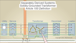
Where there are multiple transformer SDSs, a GEC tap from each of them to a common GEC is permitted [Sec. 250.30(A)(6)]. This connection must be made at the same point on the transformer SDS secondary as where the system bonding jumper is connected [Sec. 250.30(A)(1)], as shown in Fig. 3.
The common GEC can be any of the following [Sec. 250.30(A)(6)(a)]:
(1) An unspliced conductor at least 3/0 AWG copper or 250kcmil aluminum.
(2) Interior metal water pipe not more than 5 ft from the point of entrance to the building [Sec. 250.68(C)(1)].
(3) The metal frame of the building per Sec. 250.68(C)(2) or connected to the grounding electrode system by a conductor at least 3/0 AWG copper or 250kcmil aluminum.
GEC taps must be sized per Table 250.66, based on the area of the largest secondary phase conductor [Sec. 250.30(A)(6)(b)].
Exception: If the only electrodes present are ground rods [Sec. 250.66(A)], concrete-encased electrodes [250.66(B)], or ground rings [Sec. 250.66(C)], the size of the common GEC is not required to be larger than the largest conductor required by Sec. 250.66(A), (B), or (C) for the type of electrode that is present.
Tap connections to the common grounding electrode conductor must be made at an accessible location by any of the following methods [250.30(A)(6)(c)]:
(1) A connector listed as “bonding and grounding equipment.”
(2) Listed connections to aluminum or copper busbars at least ¼ in. thick × 2 in. wide, and of a length to accommodate the terminations necessary for the installation.
(3) Exothermic Welding. Tap GECs must remain without a splice or joint.
If located outdoors, the grounding electrode connection must be made at the transformer SDS [Sec. 250.30(C)].
The GEC must comply with Sec. 250.64(A), (B), (C), and (E) [Sec. 250.30(A)(7)]. For example, the GEC must be copper within 18 in. of the surface of the earth [Sec. 250.64(A)], securely fastened to the surface on which it is carried [Sec. 250.64(B)(1)], and adequately protected if exposed to physical damage [Sec. 250.64(B)(2) and (3)]. Also, ferrous metal enclosures enclosing a GEC must be made electrically continuous from the point of attachment to cabinets or equipment to the grounding electrode
[Sec. 250.64(E)].
Ensuring success with SDS
While a source might be separately derived, the rules for grounding and bonding it are not derived from some separate set of physics. Keep two principles in mind when bonding and grounding any SDS.
First, we ground at the source but not on the load side. That is why there’s a grounding connection at an SDS. Second, we bond so there is no difference in potential between non-current-carrying metallic objects.
About the Author

Mike Holt
Mike Holt is the owner of Mike Holt Enterprises (www.MikeHolt.com), one of the largest electrical publishers in the United States. He earned a master's degree in the Business Administration Program (MBA) from the University of Miami. He earned his reputation as a National Electrical Code (NEC) expert by working his way up through the electrical trade. Formally a construction editor for two different trade publications, Mike started his career as an apprentice electrician and eventually became a master electrician, an electrical inspector, a contractor, and an educator. Mike has taught more than 1,000 classes on 30 different electrical-related subjects — ranging from alarm installations to exam preparation and voltage drop calculations. He continues to produce seminars, videos, books, and online training for the trade as well as contribute monthly Code content to EC&M magazine.