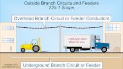
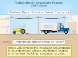
Article 225 contains requirements for outside branch circuits and feeders not over 1,000VAC or 1,500VDC, installed on or between buildings, structures, or poles (Fig. 1).
Conductors installed outdoors can serve many purposes, such as lighting and power for outdoor equipment or providing power to separate buildings.
For overhead spans up to 50 ft long, you can use conductors 10 AWG and larger. For spans over 50 ft, the minimum size conductor is 8 AWG, unless supported by a messenger wire
[Sec. 225.6(A)(1)]. The reason for these size requirements is the need for adequate mechanical strength to support the weight of the conductors and to withstand wind, ice, and other similar conditions.
Overhead conductors for “festoon lighting” cannot be smaller than 12 AWG and must be supported by messenger wire (with strain insulators) whenever the spans exceed 40 ft long [Sec. 225.6(A)(B)].
The point of attachment for overhead conductors to buildings must be at least 10 ft above the finished grade. You may need to raise the point of attachment so the overhead conductors will comply with the clearances from building openings and other building areas required by Sec. 225.19 [Sec. 225.16(A)]. It’s wise to look for an alternate route that avoids these conflicts.
Open conductors must be attached to buildings by fittings identified for use with conductors or to noncombustible, nonabsorbent insulators securely attached to the building [Sec. 225.16(B)].
Supports
Any mast for the support of overhead conductors must have adequate strength, braces, or guy wires to safely withstand the strain caused by the overhead conductors [Sec. 225.17(A)]. Overhead conductors cannot be attached to a mast between a weatherhead and a coupling located above the last point of securement or where the coupling is above the roof [Sec. 225.17(B)].
You cannot use vegetation to support overhead conductor spans [Sec. 225.26].
Clearance for overhead conductors
Overhead conductor spans must maintain clearances as outlined in Sec. 225.18. For example, they must be 18 ft over public streets, alleys, roads, parking areas subject to truck traffic, driveways on other than residential property, and other areas traversed by vehicles such as those used for cultivation, grazing, forestry, and orchards.
They must also maintain vertical and horizontal clearances from buildings as outlined in Sec. 225.19. For example:
- Vertical clearance of 8 ft, 6 in. above the surface of a roof for at least 3 ft from the edge of the roof.
- Clearance of at least 3 ft from signs, chimneys, radio and television antennas, tanks, and other nonbuilding structures; and from windows that open, doors, porches, balconies, ladders, stairs, fire escapes, or similar locations.
Raceways
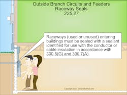
Raceways on exteriors of buildings must be arranged to drain and be listed or approved for use in wet locations [Sec. 225.22]. Where an outside raceway enters a building, it must be sealed with a sealant that is identified for use with the conductor insulation [Sec. 225.27], as shown in Fig. 2.
When feeders supply buildings
A building can be supplied by only one feeder, except as permitted in Sec. 225.30(A) through (F). For example, you can use additional feeders to supply fire pumps and emergency systems. Other examples are when you have different voltages, frequencies, or uses, such as controlling outside lighting from multiple locations.
Disconnecting means
A disconnect is required for all feeders that supply, enter, or pass through a building [Sec. 225.31(A)].
Install the feeder supplied disconnect at a readily accessible location, either outside or inside the building nearest the point of entrance of the conductors [Sec. 225.31(B)]. Feeder conductors under at least 2 in. of concrete or encased in at least 2 in. of concrete are considered outside a building in accordance with Sec. 230.6.
The building feeder disconnecting means can consist of no more than six switches or six circuit breakers in a single enclosure or in separate enclosures grouped together
[Sec. 225.33(A)].
The building feeder disconnecting means must be grouped in one location and marked to indicate the loads they serve [Sec. 225.34(A)].
To minimize the possibility of accidental interruption of critical power systems, the disconnect for a fire pump, emergency systems, legally required standby systems, or optional standby systems must be installed remotely from the normal power disconnect
[Sec. 225.34(B)].
Identify multiple supplies
If a building is fed by more than one feeder or service, a permanent plaque or directory must be installed at each feeder disconnect location denoting all other feeders and services supplying that building and the area served by each [Sec. 225.37].
This information is critically important to first responders who almost certainly will not be familiar with the electrical distribution system of the facility but will need to disconnect power to the building during an emergency.
The feeder disconnect must meet minimum ampere ratings per Sec. 225.39(A) through (D).
- Single branch circuit: 15A
- Two 2-wire branch circuits: 30A
- One-family dwelling: 100A
- Other installations: 60A
Emergency disconnects
For one- and two-family dwellings, an emergency disconnect must be installed at a readily accessible outdoor location on or “within sight” of the dwelling unit [Sec. 225.41(A)(1)]. The emergency disconnect must have a short-circuit current rating equal to or greater than the available fault current [Sec. 225.41(A)(2)]. If more than one emergency disconnect is provided at a building, they must be grouped [Sec. 225.41(A)(3)].
Where disconnects for other energy source systems are not adjacent to the emergency disconnect, a plaque or directory identifying the location of other energy source disconnects must be adjacent to the emergency disconnect [Sec. 225.41(B)]. See Secs. 445.18, 480.7, 705.20, and 706.15 for examples of other energy source system disconnecting means.
The emergency disconnect must be marked “EMERGENCY DISCONNECT“ [Sec. 225.41(C)]. Markings must be permanently affixed and be sufficiently durable to withstand the environment involved per Sec. 110.21(B). The emergency disconnect marking or label must be on the outside front of the disconnect with a red background and white text, and the letters must be at least 1/2 in. high.
Surge protection
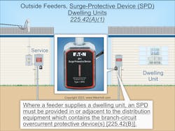
Where any of the following occupancies are supplied by an outside feeder, a surge protective device (SPD) is required [Sec. 225.42(A)]:
- Dwelling units (Fig. 3)
- Dormitory units
- Guest rooms and guest suites of hotels and motels
- Areas of nursing homes and limited-care facilities used exclusively as patient sleeping rooms.
The feeder SPD must be either Type 1 or Type 2 [Sec. 225.42(C)], and have a nominal discharge current rating (In) of at least 10kA [Sec. 225.42(E)].
Where feeder supplied distribution equipment is replaced, an SPD is required for the distribution equipment [Sec. 225.42(D)].
Install it in (or adjacent to) feeder distribution equipment [Sec. 225.42(B)]. Surges can be generated from lightning, the electric utility, or utilization equipment. Surge protection is most effective when installed closest to the branch circuit(s) with lead lengths of conductors to the SPD kept as short and straight as is practical. See Parts I and II of Art. 242 for installation requirements that apply to SPDs.
Pro tip
To ensure an outside conductor installation that is both Code-compliant and completed To ensure an outside conductor installation is both Code compliant and completed efficiently, actively look for alternatives to your original plans before sending them out to the field. This takes time and some thinking, but the payoff can be big.
For example, it looks like you save money on conductors in your bill of materials by using the most direct and obvious path when routing. But if that path takes you over a balcony or through some trees when you could instead go around them, you will have a more complex installation that carries higher material costs, longer installation time, and higher risk of a Code violation — and probably higher maintenance costs.
Using a different path, you could reduce the complexity and thus the total installation cost and the total lifetime cost — even if it’s longer and uses more materials. Maybe going around the east side of the building instead of the west side would eliminate half a dozen clearance concerns.
Map out the location of every connection point, and then decide the conductor routing between those points based on what is actually there. Consider what is above, below, and adjacent to the proposed routing.
About the Author

Mike Holt
Mike Holt is the owner of Mike Holt Enterprises (www.MikeHolt.com), one of the largest electrical publishers in the United States. He earned a master's degree in the Business Administration Program (MBA) from the University of Miami. He earned his reputation as a National Electrical Code (NEC) expert by working his way up through the electrical trade. Formally a construction editor for two different trade publications, Mike started his career as an apprentice electrician and eventually became a master electrician, an electrical inspector, a contractor, and an educator. Mike has taught more than 1,000 classes on 30 different electrical-related subjects — ranging from alarm installations to exam preparation and voltage drop calculations. He continues to produce seminars, videos, books, and online training for the trade as well as contribute monthly Code content to EC&M magazine.