The power quality of electrical distribution systems has a drastic effect on power regulation and consumption. Power quality includes all aspects of events in the power system that deviate from normal operation, which includes harmonics.
Harmonics is distortion on a power system caused by nonlinear-type loads, such as variable-frequency drives (VFDs), large computer systems, SCADA systems, electronic lighting ballasts, etc. In some facilities, these types of loads account for a significant portion of the total load. IEEE Standard 519-2014, “Recommended Practice and Requirements for Harmonic Control In Electric Power Systems” sets the requirements for harmonics and creates limits for harmonic distortion. There are also several different ways that harmonic distortion can be mitigated.
What exactly are harmonics? Essentially, harmonics are a mathematical way of describing distortion to a voltage or current waveform. However, understanding the math is not important. Rather, it’s important to understand that harmonics are a steady-state phenomenon and repeats with every cycle.
Defining Harmonics
Harmonics should not be confused with transient dips, spikes, impulses, oscillations, etc. Also, the term “harmonic” refers to a component of a waveform that occurs at an integer multiple of the fundamental frequency.
Harmonic distortion is the degree to which a waveform deviates from its pure sinusoidal values as a result of the summation of all the harmonic elements. An ideal sine wave would have zero harmonic components. For a 60-Hz fundamental frequency waveform, the 2nd, 3rd, 4th, and 5th harmonic components will be a 120 Hz, 180 Hz, 240 Hz, and 300 Hz, respectively.
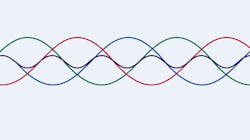
Looking at Fig. 1A, you can see how the waveform does not have any harmonic components and is essentially a pure sinewave with linear loads. Linear loads draw current that is sinusoidal in nature so they generally do not distort the waveform.
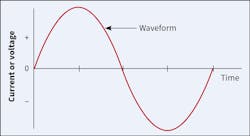
Looking at Fig. 1B, however, you can see how nonlinear loads can draw current that is not perfectly sinusoidal. Since the current waveform deviates from a sinusoidal wave, voltage waveform distortions are created. So, as you can see, distortions can drastically alter the shape of the sinusoidal waveform. However, no matter the level of complexity of the fundamental waveform, it is just a composite of multiple waveforms called harmonics.
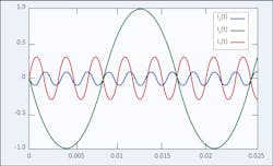
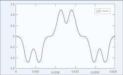
Figures 2A and 2B show how the harmonic components combine to form a resultant waveform with much distortion. Figure 2A shows the fundamental frequency waveform, the 5th harmonic waveform and the 7th harmonic waveforms. Figure 2B shows the combined resultant waveform of the three individual waveforms in Fig. 2A.
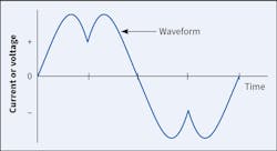
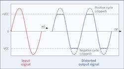
Figure 3 illustrates a nonlinear waveform that shows “clipping.” This type of waveform is common in electronic devices having nonlinear characteristics, such as computer-based equipment. When the sine waves are distorted symmetrically about their average values, then they are composed of odd harmonics only.
Power is supplied by a 3-phase system, where each phase is 120° apart. This is done for two reasons. First, it is because motors and/or generators that use 3-phase power are more efficient due to the constant torque the phases supply. Second, it is because after power is supplied to a load, the three phases can theoretically be added onto a neutral wire and cancel each other out. This saves the electric utility from adding return wiring to the power plant.
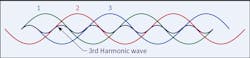
However, if the three phases contain 3rd order harmonics, the currents will not fully add to zero (or cancel out). As you can see in Fig. 4, the 3rd harmonics between the phases add together, which creates oscillating current. This results in a sharp increase in the zero-sequence current, which increases the current in the neutral conductor. This effect can require special consideration in the design of an electric system to serve nonlinear loads. To avoid 3rd order harmonics adding together, delta connections are used, and the current is cycled around the connection instead of a wye connection. Most harmonic problems are caused by the 3rd harmonic.
Negative Consequences
Harmonics can have detrimental effects on electrical equipment and power systems. Unwanted distortion can increase the current in power systems, which results in higher temperatures in neutral conductors and distribution transformers. Harmonics can cause the overheating of transformers, motors, generators, capacitors, cables or conductors, etc., which can result in premature failure. Harmonics can also cause misoperation of circuit breakers and other protective devices, as well as malfunction of electronic equipment. Some of the other effects of harmonics are as follows:
• Results in incorrect readings on meters, which can cause another set of other problems and can also cause malfunction in instruments, including medical instruments.
• Premature failure of power supplies due to the distortion of the supply voltage.
• Low power factor, requiring a transformer to be upsized in kVA or neutral upsizing.
• Resonating and heating of power factor correction capacitors, which can cause failure.
Resonance
Another phenomenon related to harmonics that can occur is system resonance. The single largest cause of severe harmonic distortion is resonance. Resonance occurs when a harmonic frequency produced by a nonlinear load closely coincides with a power system natural frequency. The likelihood of effects from harmonics occurring greatly increases if a resonant condition exists or occurs. A normal harmonic may be amplified 10 to 25 times if resonance occurs at or near critical frequencies. Resonance occurs mainly due to improper use of power factor correction capacitors or because of incorrect application of filters. There are two forms of system resonance: parallel resonance and series resonance.
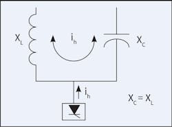
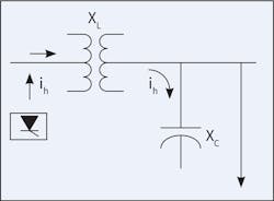
Parallel resonance (Fig. 5) occurs when the system inductive reactance (noted as XL) and capacitive reactance (noted as XC) are equal at some frequency (5th, 7th, etc.). Harmonic currents that flow between capacitors and the system inductance are significantly amplified (typically up to 10 to 15 times). Parallel resonance can lead to capacitor fuse blowing or failure and/or transformer overheating.
Series resonance (Fig. 6) is a series combination of inductance and capacitance. It creates a low-impedance path for harmonic currents at the natural frequency. This results in high harmonic currents through the capacitors. Series resonance can result in a high-voltage distortion level between the inductance and capacitance.
Guidelines and Direction
IEEE Standard 519-2014, “Recommended Practice and Requirements for Harmonic Control in Electric Power Systems,” was created to establish limits for harmonic distortion and provide direction on dealing with harmonics. It was intended to provide direction on dealing with harmonics introduced by static power converters and other nonlinear loads. The standard was written to establish goals for the design of electrical systems with both linear and nonlinear loads. It is presented as a guideline for power system design when nonlinear loads are present and assumes steady-state operation. Distortion limits for both current and voltage are defined to minimize interference between electrical equipment. The limits are defined at the point of common coupling (PCC).

The PCC is defined as the point in the power system closest to the user where the system owner or operator could offer service to another user. Frequently for service to industrial users (e.g., manufacturing plants) via a dedicated service transformer, the PCC is at the high-voltage side of the transformer, as shown in Fig. 7A. For commercial users that are supplied through a common service transformer, the PCC is commonly at the low-voltage side of the transformer, as shown in Fig. 7B. The PCC is basically recognized as the point where any harmonics could migrate onto the electric utility system and cause problems for other customers.
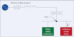
The PCC is essentially the point at which another customer could be served. The intention of having a PCC is to prevent a high level of harmonics (such as that generated by nonlinear loads) generated by one customer from causing distortion at another customer’s distribution system on the power grid. In considering the primary side of a power transformer (that supplies only one customer), the transformer’s impedance will decrease the short-circuit ratio. This results in an increase in the harmonic current limits. The voltage distortion will be higher at the secondary of the transformer.
Calculating THD and TDD
How do you show how much harmonic distortion there is on a system? Here are the equations you use to calculate total harmonic distortion (THD) and total demand distortion (TDD).
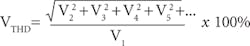
Total harmonic distortion (THD):
(Where IDn is the magnitude of the nth harmonic)
Total demand distortion (TDD):
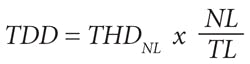
(Where TDD = TDD of the system, THDNL = THD of nonlinear loads, NL = kVA of nonlinear loads and TL = kVA of total load)
These equations can be used to describe voltage or current distortion. The total demand distortion equals the total harmonic distortion multiplied by the ratio of nonlinear load to the total demand load (which includes both linear and nonlinear loads). Per the IEEE 519 standard, these equations consider harmonic components up to the 50th order, however components of order greater than 50 may be considered if necessary.
The voltage THD of the waveform is the ratio of the root-sum-square value of the harmonic content of the voltage to the root-mean-square value of the fundamental voltage.
The current THD of the waveform is the ratio of the root-sum-square value of the harmonic content of the current to the root-mean-square value of the fundamental current.
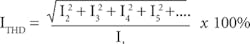
These formulas show the THD on a signal. The result is a percentage comparing the harmonic components to the fundamental component of a signal. The higher the percentage, the more distortion that is present on the signal.
Managing Harmonics
Since managing harmonics in a power system is considered a joint responsibility, involving both the supplier and the end-users, IEEE 519 places recommended harmonic limits for both voltage and current. The recommended values are based on the fact that some level of voltage distortion is generally acceptable, and both parties must work together to keep actual values within acceptable levels. By limiting the harmonic currents by users, the voltage distortion can be kept within acceptable levels.
IEEE 519 also states that the recommended limits only apply at the PCC and are not to be applied to individual pieces of equipment or at locations within a user’s facility. In most instances, the harmonic voltages and currents at these locations can be found to be significantly greater than the limits at the PCC due to the lack of cancellation or other phenomena that tend to reduce the combined effects of multiple harmonic sources.
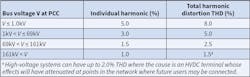
Table 1 is a replication of Table 1 in IEEE Standard 519-2014, which establishes harmonic limits on voltage as 8% for THD and 5% of the fundamental voltage for any single harmonic, for system levels up to 1,000V. The limits for system levels between 1,000V and up to 69kV have harmonic limits on voltage as 5% for THD and 3% of the fundamental voltage for any individual harmonic. You’ll also notice it shows limits for voltage levels up to 161kV.
It should be noted that even if the voltage distortion limits are met at the PCC, they could very easily be exceeded downstream where connected equipment could be affected. Since voltage distortion is the result of harmonic currents passing through the impedance of the power system, voltage distortion is always higher downstream where the harmonic currents are generated and where system impedance is the highest.
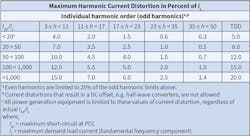
Table 2 is a replication of Table 2 in the standard, showing the current distortion limits for power systems with voltage levels between 120V and 69kV. The table defines TDD (current) limits as well as individual harmonic current limits. The limits are most severe for short circuit ratios of less than 20 because this lower ratio indicates a high impedance power system, a large customer, or both. Voltage distortion is more likely to develop from current harmonics consumed at a PCC where the short circuit ratio is low, thereby justifying the more severe limits. Tables 3 and 4 from the standard (not shown) also show the current distortion limits for higher system voltages.
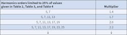
It is recommended that the current harmonic distortion limits be increased by a multiplying factor when actions are taken by the user to reduce low-order harmonics. As we see in Table 3, the multipliers in the second column are to be used when steps have been taken to reduce the harmonic orders shown in the first column. Please note, however, that the low-order harmonic components must be kept below 25% of the current harmonic distortion values shown in Table 2.
Summing It Up
Harmonics are distortion on a power system caused by nonlinear-type loads. Causes of harmonics can be VFDs, large computer and SCADA systems, electronic lighting ballasts, arc welders, heaters and furnaces, DC converters, UPS systems, etc. Most issues caused by harmonics are caused by the 3rd harmonic. Effects of harmonics can be overheating of electrical components and equipment, equipment malfunction and/or failure, incorrect readings on meters or instruments, and system resonance. IEEE Standard 519 sets the requirements for harmonics and creates limits for harmonic voltage and current distortion. IEEE 519 states that the recommended limits only apply at the PCC; however, the harmonic voltages and currents at downstream locations can be found to be significantly greater than at the PCC. Voltage distortion is always higher downstream where the harmonic currents are generated and where system impedance is the highest.
Downey is the principal engineer for AVO Training Institute (www.avotraining.com). He is an active member of the IEEE 1584 Working Group – Guide for Performing Arc-Flash Hazard Calculations, and IEEE 1814 Working Group – Recommended Practice for Electrical System Design Techniques to Improve Electrical Safety. He also serves as an alternate on the NFPA 70E Technical Committee. He can be reached at [email protected].
Sidebar: Devices and Components That May Cause Harmonics Issues
Following is a list of devices or components that can cause issues with harmonics:
• Variable-frequency drives (VFDs)
• Universal power supply (UPS) systems
• DC converters
• Solid-state rectifiers
• Arc welders
• Heater units or furnaces
• Switch-mode power supplies (such as those used on computers)
• Electronic lighting ballasts
• PLC systems, SCADA systems, computer systems, etc.
About the Author
Ryan Downey, P.E.
Downey is a principal engineer for AVO Training Institute (www.avotraining.com). He is an active member of the IEEE 1584 Working Group – Guide for Performing Arc-Flash Hazard Calculations and IEEE 1814 Working Group – Recommended Practice for Electrical System Design Techniques to Improve Electrical Safety. He can be reached at [email protected].