The Case of the Chiller Fuse Failures
It was early fall in Southern California when a university began to have problems with 480V fuse failures on a large chiller located in the central plant. Multiple failures occurred within two months, and the school's maintenance team was anxious to find the cause.
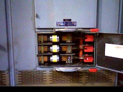
The facility was fed by a 12kV feeder that connected to a primary electric utility meter. From the primary meter, the university installed and operated the campus electrical distribution system and 12kV/4,160V and 4,160V/480V transformers on the campus. The 480V switchgear feeding the chiller was located in the same room as the chiller, approximately 15 ft away.

The first step was to obtain voltage readings at both the 12kV level (requiring assistance from the electric utility) and at the 480V switchgear in the central plant. The intent was to identify if the voltage at both locations was within ANSI C84.1 Table 1 values and if voltage imbalance was present. Both undervoltage and voltage imbalance will contribute to fuse failures. In this case, the voltage was within spec of the equipment and ANSI C84.1 Table 1. The voltage imbalance was recorded at 0.76%, well below the contribution point to cause fuse failures.
Next, a millivolt drop test was performed with a standard calibrated true RMS digital voltmeter. The purpose of testing across contacts, terminals, lugs, and bus splices is to detect a higher resistance in comparison to the other points measured in the same location. The higher the resistance, the more voltage drop occurs across that terminal point. If the millivolt drop test is unsuccessful, then a digital low-resistance ohmmeter can provide a more accurate resistance reading. The line side of the fused disconnect was measured with the chiller running. The following values were obtained:
- Phase A ― 191mV (350A)
- Phase B ― 97mV (355A)
- Phase C ― 63mV (348A)
These measurements raise suspicion of a problem on Phase A.
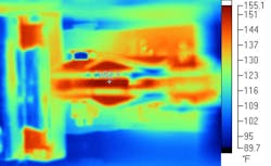
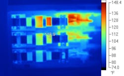
Finally, a thermal imaging camera was used to evaluate the chiller fused disconnect. Phase A read the highest temperature, as suspected. The temperature at the line side fuse clip was 138˚ to 152˚F. Phase B and Phase C were 118˚F and 89˚F, respectively.
There were two problems identified here:
- High resistivity in the fuse clip is heating the fuse element close to the blow curve.
- The ambient temperature of the fused disconnect and the central plant room was very high. Most fuse manufacturers set the fuse amperage blow curve to 77˚F. The fuse must be derated for temperatures higher than 77˚F.
The root cause of the premature fuse failures was tied to two problems that compounded: heat caused by resistance and high ambient temperature lowering the fuse blow curve. The current of the chiller was within operating parameters and not causing an overcurrent condition. By using the thermal imaging camera, the solution was identified within a short time after beginning the troubleshooting process.
Think outside the box when troubleshooting, and use all the tools you have available will help to identify the solution quickly.
About the Author
Bryan Glenn
Power Quality Consultant
Bryan Glenn is a power quality consultant for EC&M magazine. He can be reached at [email protected].