HISTORY: High Resistance Grounding is a means of limiting ground fault current in electrical systems. Unrestrained fault current can cause severe equipment damage, product destruction, and personnel injury. This article will address the history, use, and recent developments in available high resistance grounding technology used with ungrounded voltage systems.
High Resistance Grounding is generally defined as a grounding system device in which the maximum available fault current is held to <10 Amps. High resistance Grounding can be established by using grounding transformers; singular, or in arrays. There are two types of transformers[1] used in high resistance grounding, shown in Figure 1, a WYE Broken Delta Array, and a Zig-Zag transformer. It is important to note that the WYE Broken Delta (WBD) array does not place resistance in the voltage system neutral for control of fault current, while the Zig-Zag transformer does. This article will focus on the development of the WBD technology and bring to light new designs from EM Energy Solutions, emenergysolutions.com.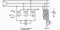
Figure 1: High Resistance Grounding Transformer Types.
WBD High Resistance Grounding can be implemented at low, medium, and high voltage systems, in any environment. Land based commercial entities, maritime; both ships and offshore platforms. It is well suited for back-fitting into existing systems and is an excellent means of improving worker safety as well as increasing production by reducing unscheduled down time. Figure 2 shows WBD High Resistance Grounding for Medium Voltage systems[2].
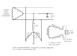
Figure 2: WBD Implementation at Medium Voltage
TESTING WBD SYSTEMS: Consider the task of a theoretical Plant Engineer hoping to improve plant production (be a hero), comply with OSHA needs, and improve worker safety. Why not attempt a trial installation of a suitable WBG High Resistance Grounding system, and test it? Well, is the only option to purposely insert a ground fault into a functioning plant electrical system, and “see what happens”? Management may not approve this approach. Best not to insert a ground fault, but one possibility is to observe the system voltages as the theoretical new WBD is switched into the plant voltage system, already with some degree of ground fault.
Figure 3 shows the results of this actual trial in a commercial manufacturing plant.
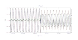
Figure 3: WBD Switched into System with severe B-Phase ground
It must be noted that a previously little-known effect of WBD grounding arrays is that it may actually “recover” the missing (grounded) phase voltage. Figure 4 shows this and the actual transition time in which this occurs.
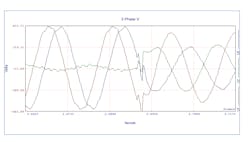
Figure 4: Transition Time of WBD to Restore Grounded Phase
The time to recover the grounded voltage seems to be dependent on two factors; total system stray capacitance and distance to the actual point of fault. In this example, the transition occurred in slightly less than 1 milli-second. Figure 5 shows the transition waveform expanded.
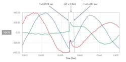
Figure 5: Voltage Recovery Time
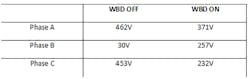
Table 1 shows the comparison of systems voltages measured with respect to ground.
Table 1: Voltage Recovery
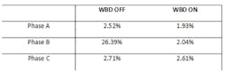
FAULT INDUCED HARMONICS: During a ground fault, voltage harmonics on the grounded phase may become excessive. Such harmonics will be felt across all loads on the voltage system. WBD arrays are useful for suppressing such “fault mode” harmonics. While it may be commonly understood that one useful aspect of using an ungrounded voltage system is that minor faults can be left on the system until it is convenient to power down as needed to isolate the point of failure, recall that harmonics cause excessive heating; thus shortening the life cycle of power capacitors, motors, and transformers. Table 2 (above) shows the result of WBD usage during the above ground fault shown in Figure 3. The WBD can reduce the impact of ground fault harmonics until the fault is isolated and cleared.
WBD Grounding Transformer arrays do not carry load current, they are installed as a parallel system, as close to the voltage source as practicable. While they may reduce harmonics during a ground fault, they do not add to system fault current calculations as do fixed tuned harmonic filters.
However, several issues with legacy WBD arrays need to be considered and understood:
False or No Alarm:o The primary side X0 bond of the WBD may cause false ground fault alarms when a WBD is back-fitted into a voltage system using a Pulsing DC Ground Fault Monitoring System. o The voltage balancing action of the WBD may render any ground fault indicator light system incapable of showing low level faults. A better class of instrumentation is needed.DC Offset:
o When a WBD Grounding Transformer is installed in a voltage system utilizing Variable-Speed Drives, large DC faults can occur. This is particularly hazardous in a Maritime environment. Again, the WBD X0 bond can become a path for DC offset of the system AC voltages.Previous Limits:
o Legacy WBD arrays may provide a temporary stopgap, reducing the effects of a ground fault, but generally do not restore balanced phasors, may not identify the faulted phase, and have no means of balancing the phase voltages before the ground fault is isolated and repaired. This usually requires system downtime for fault isolation.
RECENT DEVELOPMENTS: There is new, emerging WBD technology now becoming available. Historically, WBD Grounding Transformer arrays utilize fixed instrument transformers. However, EM Energy Solutions, LLC, Automatic Voltage Equalizer (AVE) Grounding transformer arrays are now becoming available using servo driven autotransformers instead of fixed isolation transformers. In addition, a Power Quality Monitor (PQM) and a precision servo system is also incorporated into the AVE, as well as a Communication (Modbus and Bluetooth) package. The action of the on-board PQM is to; 1) monitor voltage system activity, and 2) to provide voltage, current, and phase angle information to the servo controller. This raw data is then processed to enable the servo system to re-balance the system voltages and phase angles. As this is happening, the Modbus is used to notify the system operator of changing conditions.
This approach is able to perform ground fault mitigation in two succinct steps. Since a ground fault on ungrounded voltage systems causes the grounded phase to SAG, the remaining two ungrounded phases can SURGE to severe over-voltages. This may be longer than can be mitigated without damage by conventional Surge Protective Devices (SPDs). So, the AVE can act as both a SAG and SURGE mitigation device.
First, the normal WBD action of phase voltage recovery occurs, generally in 1 – 2 milliseconds. Second, the imbedded sensors (within the AVE array), provide inputs for the AVE servo controller to re-position the autotransformers to restore phase voltage balance. This is seen to occur in 2-3 seconds. Figure 6 shows this occurrence, taken at a large shipyard automated welding site.
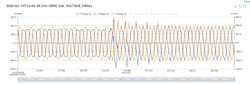
Figure 6: Action of Dynamic WBD Grounding Array
The waveform log above is captured by the internal Power Quality Monitor within the AVE during automated welding machine operation and shows the exact moment when the AVE activated. The waveform before the AVE activation is distorted with a high voltage unbalance (8-9%). After AVE activation, we see a short transitional period of 30-40ms where the unit stabilizes the system, removes harmonic distortion, eliminates transients, and reduces voltage unbalance (0.5%). Finally, after the AVE is activated, we can see a perfect three-phase sine waveform and a 100% balanced system.
SUMMARY:
The AVE array is not subject to the shortcomings of traditional WBD array designs. The AVE is:
- Compatible with Pulsing DC Ground Fault Monitoring systems. False alarms will not be generated.
- Immune to DC Offset should a DC downstream load fault occur.
- Capable of system voltage and phasor balancing.
- Presents a sub-cycle reaction time with no “ride-thru” limitations. Thus, a multi-day batch process could be maintained as needed without potential product loss.
The AVE array PQM incorporates communication protocols, MODBUS and Bluetooth. Thus, the system operator can be notified of ground fault issues, accompanied by identification of the faulted phase. When such a unit is provided with an optional distributed net current monitoring system, the faulting phase, and also the associated electrical load can be identified.
An AVE from EM Energy Solutions accomplish a range of cost saving improvements.
- Total fault analysis time is reduced.
- Worker safety is improved.
- Harmonics (line to ground) are reduced, electrical component service life-spans are increased.
- Voltage Sags and Surges are eliminated.
- Arc-Flash hazards are greatly reduced.
- Reactive currents are greatly reduced.
- Batch processes need not be suddenly taken offline, saving product and operating costs.
Should Power Quality issues such as; Low Power Factor (pf), Phase Current imbalance, High Harmonic distortion, also exist; EM Energy Solutions can provide additional new technology building blocks in concert with an AVE for a total Power Quality upgrade package. EM Energy Solutions has developed an entirely new family of active voltage and current control solutions for the Power Quality industry.
Additional sub-units can be provided such as the ACTIVE HARMONIC FILTER (APF). The Active Power Filter provides harmonic cancellation. The STATIC VAR GENERATOR (SVG) provides sub-cycle VAR Compensation.
In this way, voltage and current balancing, power factor correction, and Harmonic reduction capability can be provided to any industrial process.
EM Energy Solutions products can be provided for Low, Medium, and High Voltage applications.
Sponsored by:EM ENERGY SOLUTIONSElectromagnetic Energy Solutionswww.emenergysolutions.comFerjemannsveien 4 7042 Trondheim Norway
Contact:
[email protected] Phone: +47 97 56 07 56[email protected] Phone: +47 41 44 56 16
UNITED STATES
Borg General Sales
1386 Jarvis Ave
Elk Grove Village, Ill
Contact:
[email protected]
847-645-4635
847-640-7934(fax)
[1] Grounding of Marine Electrical Power Systems: A True Perspective, D.D. Shipp, Westinghouse Corp., C.O. Craps, U.S. Navy, Washington, DC, T.M. Nolan, US Coastguard, Washington DC, SNAME 1981.
[2] Baldwin Bridger, Jr. Senior Member IEEE, IEEE Transactions on Industry Applications, Vol. 1A-19, No. 1, January/February 1983.