Preventive Measures for UPS Systems

Instrumentation and control systems in petrochemical facilities require an extremely reliable source of power. The backup power supply should be available for an adequate period in the event of an electric utility power outage or until an emergency generator is started (if available).
The design criteria for critical power equipment can be defined as follows:
- Ability to provide emergency power during interruptions or loss of normal power, up to a designated time (usually determined by the time necessary to safely shut down a facility during a power outage)
- Unaffected by outside events (transients, surges, etc.).
- Robust performance (low risk of failure).
- Robust internal system design — rapid isolation of internal failures, with means to supply alternate power (if supplied and available) without interruption.
Uninterruptible power supply systems (UPSs) are typically installed to provide power that meets these requirements. Photo 1 shows a typical industrial system comprised of a UPS unit and associated battery bank.

In many instances, much emphasis is placed purchasing exceptional (and expensive) UPS equipment while minimal or no attention is placed on the other components of the critical power system. Inattention to these items can compromise the reliability of this equipment, even rendering the reliability of the most expensive and reliable UPS unit marginal.
As discovered in the case of one industrial facility, the lack of attention to these peripheral details resulted in costly shutdowns and lost production, that could have been prevented with a few minimal changes. Ultimately, the cost to correct the overlooked details was a fraction of the lost production cost.
Initiating event (2001)
In 2001, a chemical processing unit (CHEM1) at a major industrial petrochemical facility suffered a complete unit shutdown when one of five UPS units servicing that facility lost output power. The shutdown occurred after a loss of input power from a 480V distribution panel that supplied normal input power to four of the five units for this facility.
Normally, each UPS would have continued to supply power from its batteries. However, one of the UPS units lost output power after one of the cells failed in the unit’s DC battery bank during the subsequent discharge.
Initial failure investigation
An investigation was performed to determine what caused the initial loss of the power supply to the 480V distribution panel and UPS equipment. The 480V panel supplied several non-critical loads in addition to the UPS equipment (e.g., HVAC units and lighting/convenience receptacles for the adjacent computer room). See Fig. 1 for the existing power distribution layout. Four of the five UPS units were supplied from one 480V distribution panel, including the failed unit.

The investigation revealed that one of the HVAC units sustained a failure (i.e., shorted heater strip). The fuses were blown in the HVAC disconnect switch to this unit. The failure also caused the main breaker in the 480V distribution panel to trip (the branch circuit breaker remained closed). What appeared to be an apparent miscoordination of the panel breakers and the HVAC fuses warranted further investigation.
Classic case of miscoordination
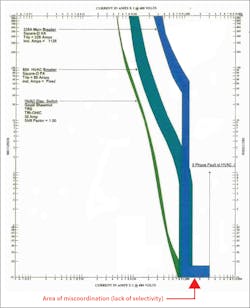
Why did the distribution panel main breaker trip instead of the branch breaker for the HVAC unit? Upon further analysis, the answer for this sequence of events was obvious and is a textbook case of a lack of selectivity for circuit breaker protection in a panel where the available fault current is high — and there is not enough separation of overcurrent device ratings to provide selectivity and coordination.
The available fault current at the 480V distribution panel was fairly high. Since the main breaker and the HVAC feeder breaker were close in size (rating), there was no coordination for a significant fault; the magnitude of fault current fell into the instantaneous region of both breakers and the fuse in the HVAC circuit (see TCC curve in Fig. 2).
While this issue is not easily corrected [it would probably require a major redesign of the panel (i.e., a new panel with a main breaker, and possibly an adjustable solid state trip unit)], a more affordable solution was to reconfigure the panel by moving the non-critical loads to other nearby electrical distribution centers, reducing the risk of exposure.
The loss of 480V power was the initiating failure; as mentioned earlier, though, the unit should have supplied power via battery discharge. This did not happen. Two additional issues ultimately caused the UPS to fail:
- Battery failure itself — The unit that failed was connected to a VRLA battery bank that failed. These banks are generally recognized as less reliable than flooded lead-acid stationary batteries. This bank had recently been maintained (i.e., tested) with no indications of underlying issues. The bank was approximately five years old.
- Separate power for normal and alternate (bypass) input sources — there was no redundancy for normal and alternate power; both sources were fed from the same 480V panel, which was also supplied by the same motor control center (MCC) and distribution transformer. In this case, the UPS output power may have been maintained if the alternate source was fed from a separate source than the normal input. The high-speed switching characteristics of the internal static switch would have switched sources without a loss of power.
As part of the event investigation, a review was performed of the other four UPS systems in this production unit to identify similar risks. The following items were discovered as potential risks, which could affect the future reliability of the emergency power for the CHEM1 UPS equipment:
- Four of the five units were supplied by VRLA battery banks.
- Lack of redundancy for normal and alternate power for all five units (i.e., normal and alternate power were fed from the same upstream source).
- Comingling of loads in the 480V primary distribution panel to the UPS (i.e., critical vs. non-critical loads, such as lighting and HVAC in the same panel as the UPS supply).
- Several of the UPS output power panels were standard commercial power panels with standard molded-case circuit breakers (MCCBs). They were not the type recommended by most UPS manufacturers (e.g., a panel with fused disconnects utilizing high-speed semiconductor fuses).
- Two of the UPS units had no remote maintenance bypass switches (also known as “wraparound“ maintenance bypass switches) to allow complete isolation of the unit. They had an internal bypass mode only. Internal repairs to these units could only be made during a plant outage.
- The five units were made by multiple manufacturers of UPS equipment — no standardization.
- Three of the UPS units were obsolete.
Immediate corrective actions for CHEM1 UPS systems

Immediate steps were taken on CHEM1 units to address three of the above issues:
- All non-critical loads were removed from the main 480V UPS power distribution panel. Three HVAC units and a building service receptacle/lighting panel were relocated to other nearby 480V power sources (i.e., panelboards located in an adjacent substation building, fed from a different transformer).
- Two of the units’ VRLA battery banks were converted to flooded lead acid. These conversions involved several steps:
- A simple reconfiguration of the battery banks, including right-sizing the existing batteries, provides more real estate in the existing UPS equipment room. One of the larger banks was reconfigured into two smaller banks. The battery size of the two new battery banks, although slightly decreased in capacity, was adequate (CHEM1 requirements for battery backup durations were met), as shown in Fig. 3a.
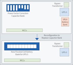
- In the adjacent MCC building where one of the UPS units was located, a large and bulky power factor correction (PFC) capacitor bank rack was removed to provide space to install a flooded lead acid battery bank. There were only a few power factor correction capacitors installed for a 1,000kVA substation. In this case, the financial impact of a loss of critical power (partial or complete CHEM1 shutdown) far outweighed the savings of PFC at the utility billing point. Also, other PFC installations at the site provided adequate PFC. It was also discovered that several of the capacitors were either non-functional or not connected (the motors were previously removed). A flooded lead acid battery bank was installed in the location where the PFC bank was previously located (see Fig. 3b).
- Since all UPS units were installed near another substation, the input supply for each unit was separated so that the bypass input was supplied by a different substation (i.e., transformer) from the normal input for all five units.
Figure 4 shows the new power distribution arrangement incorporating items 1 and 3.

Long-term strategy for site-wide evaluation
The shutdown, while unwanted, allowed extending the review to a site-wide evaluation. The findings from the initial study were then evaluated for each chemical processing facility at the site. This review led to further changes across the entire facility. The following is an in-depth analysis of these issues and the corrective plans to address them.
First, each processing unit site-wide was evaluated to determine where gaps were compared to a “best practice.” Once these concerns were identified, a site-wide capital plan was implemented to standardize all systems.
The following is a list that describes categories to be evaluated for each system (stated as a “best practice”) and whether each unit met that category:
- UPS manufacturer selection (for standardization).
- UPS architecture — review of pulse-width modulated (PWM) versus ferroresonant architecture.
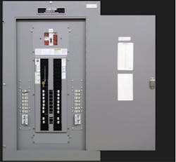
- Panel coordination — the type of panel for output power was evaluated. UPS manufacturers recommend utilizing a fused disconnect panel with high-speed semiconductor-type fuses to quickly clear output faults and minimize system disturbances for the UPS output power (see Photo 2).
- Normal and Alternate source segregation — for each unit, each source is supplied by a separate transformer/substation.
- Battery type — note the type of battery used, and is there an opportunity to upgrade?
A survey was conducted to benchmark the status of each system in several of the processing facilities, highlighting obvious gaps where improvements could be made. The representative survey results are shown in Table 1. Colors represent either “gaps” or “satisfactory” conditions against the criteria.

Corrective actions
For seven years (after the initial incident), most of the recommendations for the site-wide upgrade were implemented. Perhaps the most important upgrade was the selection of one manufacturer for standardization purposes. In some cases, the gap was recognized, but no change was made (i.e., the risk was accepted and the component marked as “satisfactory”), which is highlighted by the “yellow” score in Table 1.
Some highlights of the upgrade program to four processing units (CHEM1, CHEM5, CHEM4, and CHEM3) are as follows:
CHEM1 processing unit
The improvements (e.g., load separation, separate normal and bypass supply segregation and battery upgrades) had already been implemented for CHEM1 as previously explained.
UPS panel replacement — three of the existing eight UPS output panels were standard commercial/residential type distribution panels with MCCBs. These panels were replaced with fused disconnect switch panels to provide high-speed clearing of faults. Two of the existing panels had to be replaced with hybrid-type enclosures with custom-fabricated equipment due to the close clearances of the existing installation.
Standardization — three obsolete units were upgraded to the standardized manufacturer. Standardization provided the following benefits:
- The manufacturer selected had a history of high reliability.
- Spare parts were reduced since most of the digital control boards were common to the units, regardless of the power rating.
- One manufacturer to provide support, streamlining maintenance of the units.
- Common utilizations of one knowledge base for maintenance support.
- Operating procedures were simplified (i.e., same for all units).
CHEM5 processing unit
The UPS unit for the CHEM5 facility was faced with imminent obsolescence. The decision was made to replace the unit before it became a legacy system. Also, this unit would have required significant investment to replace spare warehouse parts where the shelf life of the boards was expired.
There were significant real estate issues involved with replacing this unit. A solution was reached by evaluating the size rating of the unit. It was discovered that the unit could be downsized (from a 15kVA to a 10kVA rating) and still meet CHEM5 backup power requirements. This allowed the installation of a smaller physical cabinet (1/2 size), which expedited and facilitated the replacement.
CHEM4 processing unit
Two older, obsolete analog PWM units with 3-phase outputs were replaced with new UPS units. The new units were single-phase output ferroresonant units, standardized with the other units made by the selected manufacturer.
CHEM3 processing unit
An older, obsolete analog PWM unit with 3-phase output was replaced with a new digital microprocessor-controlled PWM unit from the same selected manufacturer as the above units. It was decided that the use of a new PWM unit (as opposed to ferroresonant) was acceptable in this unit, as the risks offered very minor exposure. The batteries were also upgraded to a higher quality, more robust VRLA from the standard maintenance-free sealed type.

Table 2 reflects the site-wide status after the upgrades.
Results and future plans
Since the implementation of all the sitewide changes, the affected processing units (CHEM1, CHEM3, CHEM4, and CHEM5) have sustained zero production outages due to UPS issues. This performance can also be attributed to rigorous PMs performed on the systems, both UPS, and batteries. All maintenance has been performed per industry standards, best-recognized practices and, for the most part, following the manufacturer’s recommendations for maintenance.
The following examples are specific incidents that occurred after the upgrades to attest to the resiliency due to the upgrades:
A UPS output power panel (for UPS4, CHEM1) sustained a fault on one of the branch circuits due to a computer system power supply failure. The fuse in the UPS4 output panel operated to clear the fault. No other loads were lost from that panel. This can be credited to the installation of the high-speed fault-clearing fuses that were installed as part of the panel upgrade.
One of the primary 13.8kV utility power supply feeders coming into the CHEM1 plant was lost due to a fault, resulting in a complete loss of power to one of the substations providing normal power to some of the UPS units. The UPS units fed from this substation immediately went to battery. However, one cell in the unit’s DC battery subsequently failed. The unit switched to the bypass source upon DC bus failure (by design). The substation supplying the bypass source was not affected by the utility loss. While this is not the intended sequence for emergency backup, the ability to switch to an available Alternate source saved the processing unit. Before the implemented changes, this failure could have resulted in a plant shutdown or extensive rate reductions because both of the power supplies (NORMAL and BYPASS) were on the failed feeder. Note: The loss of the 13.8kV feeder only affected some of the process equipment in CHEM1, which allowed the plant to keep running but at reduced rates.
The UPS in the CHEM5 processing plant sustained a major failure (i.e., failed ferroresonant transformer). The unit switched to the alternate source (via the internal static switch) and continued to supply outpower power to the facility, resulting in no lost production. Because the unit had a wrap-around remote maintenance bypass switch, the unit was replaced with a new unit without requiring a facility outage.
Plans are being implemented to replace two of the older units in CHEM1 due to imminent obsolescence. Performance and reliability remain high, even with the older units.
General observations
While this facility chose to standardize on certain types of UPS architecture and one manufacturer as “best practices,” each end-user should decide which options best fit their manufacturing strategy. Recent advances in equipment have or could change previously adopted design strategies, even those presented in this article.
For example:
- The industry is trending away from ferroresonant-based UPS equipment to PWM units, and ferroresonant units are becoming less readily available. Several manufacturers offer PWM units that provide robust performance and reliability. Choices have to be made for the “best fit” for each user. For example, an equivalent rating PWM unit may have a smaller footprint and be more suitable for a particular installation than an equivalent ferroresonant unit.
- Although the discussion of the selection of PWM versus ferroresonant technology is outside of the scope of this paper, a couple of significant considerations are:
- For a 3-phase output PWM unit, the conductors and components will be smaller as compared to a single-phase output of equivalent rating.
- The number of components in the 3-phase PWM unit is increased as compared to a ferroresonant unit (i.e., fewer components to fail). Since newer PWM units are more robust, this concern is not as relevant as in prior years.
- VRLA batteries – the intent of this paper is not to discredit VRLA, just to recognize as with any design selection, there will be trade-offs. The end-user will ultimately have to make the final choice. If real estate is limited, VRLA may be the best choice. Adequate service from these units can be obtained if VRLA is selected but typically the maintenance requirements will increase, and the maintenance intervals can be more frequent.
Several battery manufacturers offer quality VRLA battery systems. With proper maintenance, they can provide many years of service. The reliability concerns with these units in the late ’90s/early ’00s have been addressed. As with any equipment, observe the manufacturer’s recommendations for installation and maintenance to achieve the longest service life.
One of the fallacies that the author made (at the beginning of my career, with this facility) was that each UPS unit and supplemental equipment was optimally installed — there was no “gap” or “best practice” ignored or not followed. This was, of course, an extremely false assumption. After all, the systems in each production unit had been in service for many years. They certainly would not be inadequate. They would have been periodically reviewed.
No assessment was performed to determine the state of the systems and obvious opportunities to improve them. Of course, due to organizational changes, layoffs, and retirements, a lack of continuity provided no history of previous events and failures. Unfortunately, this is a common theme in today’s manufacturing environment.
Incorrect or inadequate designs, instead of being corrected, are perpetuated over and over. Some entities — both in-house and outside consulting firms — have no operational experience and are provided no feedback or history of what they install, which leads to them continue installing inadequate designs and repeating the same mistakes. Manufacturers’ recommendations are ignored. In some cases, engineers resort to copying existing designs with no scrutiny to ensure that the existing design is not correct or flawed.
Some excellent resources (papers) are available that discuss the application and issues of UPS equipment (e.g., search IEEE by authors Cosse/Spiewak/Dunn/Bowen/Nichols). A design guide is re-printed from one of these articles, which can be found at the end of the article in the sidebar. Several items in this design guide were addressed in the upgrades presented in this piece.
Periodic reviews of all emergency power systems should be made during the life of a facility, where gaps/deficiencies can be highlighted and addressed.
While not covered in the scope of this article, enough emphasis cannot be placed on preventive maintenance (PMs). While the corrective actions discovered during PMs, at times can appear to be over-conservative, each user will have to decide whether the cost of the consequences is worth ignoring the recommendations.
Conclusion
The assumption that plant emergency electrical power systems are installed properly with optimal configuration can be a fallacy. As was demonstrated in this case study, one chemical facility’s unwanted events allowed that facility to review each critical power system. A systematic approach was presented to evaluate all existing critical power systems for suitability. Similar to re-occurring process safety reviews, each system should be periodically re-evaluated for various parameters to determine if it is adequate or whether improvements can be made.
Several UPS systems at a petrochemical facility were discussed, including upgrades and changes to the system components that significantly improved the reliability of the systems. These aspects of system design can be overlooked.
Examples have been provided that demonstrate economic benefits (no outages) received after improvements were made in an existing chemical processing unit’s critical power system.
Author’s acknowledgment
As with most successful projects, the achievements discussed in this article would not be possible without the help and collaboration of these two co-workers: Robert Schindler (retired), senior electrical engineer for implementing several of the processing unit UPS upgrades at this facility, and David Lucio, principal electrical engineer, for guidance on achieving excellence in critical power systems and implementing some of the first generations of upgrades at this facility to modernize UPS equipment.
Mark Varisco, P.E., is the lead electrical engineer for Engineering and Inspection Services. He has worked on a wide variety of power system projects, including critical power system upgrades, substation refurbishment and power quality issues and electrical system upgrades. His experience includes more than 37 years at various industrial facilities. He can be reached at [email protected].
Sidebar: UPS Distribution System – General Protection Application Summary
©Reprinted, with permission, from IEEE Transactions on Industrial Applications, Vol. 42, No. 6. “Is My UPS Distribution System Coordinated? By authors Cosse’/Speiwak/Bowen Table IV from Section IX.
- To avoid overloading UPS systems, the UPS loads should be reviewed when additional UPS loads are anticipated.
- Segregate panel loads. Connect non-UPS loads to general-purpose panels. Connect critical loads to UPS distribution panels.
- Panelboard and circuit breaker ratings should be compared with the short-circuit current supplied by the Alternate Source.
- Use the ITI curve as a benchmark for computer business equipment operation during both steady-state and transient conditions.
- Review DCS, PLC, protection relays and critical instrumentation loads (against) voltage drop/voltage restoration limits to confirm the installed equipment can tolerate, without interruption, UPS system short-circuit transients.
- To confirm successful transfer operation, UPS static switch timing and triggering parameters should be reviewed.
- When applicable, single-phase UPS systems should be specified, because single-phase UPS systems provide more short-circuit current than equivalent kVA three-phase systems. However, when critical systems require redundant DCS, PLC and SIS power supplies and only one UPS is provided, a three-phase UPS configuration may be considered.
- Ferroresonant-type inverters generally have a greater initial short-circuit current contribution during the first 0.25 to 1.0 cycles. This may assist in downstream fuse interruption, and transfer to the Alternate Source may not be required.
- UPS manufacturers recommend fast-acting current-limiting fuses for the UPS distribution systems because fast fault current interruption is provided. Consequently, instrument panels should be the fuse type, not the circuit breaker type.
- If adequate fault current is available and can be sensed by the fuse, fast-acting fuses may minimize static switch transfer to the alternate source.
- UPS internal fuse/circuit breaker configurations vary, and the specifics must be confirmed with each manufacturer. Also, the manufacturer should confirm the alternate source magnitude does not exceed the UPS alternate source rating capabilities.
- When the UPS internal fuses are the single-element current limiting type, factory fault-testing in combination with upstream and downstream dual-element fuses may be required to determine if the internal fuse is selective with the dual-element fuses. This contingency should be included in the UPS specification.
- Fuse sizes should be minimized. As an example, if a 3A fuse is adequate, a 15A fuse should not be used.
- Typically, fuse selectivity is achieved by using fuse selectivity ratio tables. Fuses should be used from the same manufacturer since the fuse selectivity tables are obtained by test.
- When single-phase UPS systems are implemented, the 480V MCC data sheet shall specify a single-phase or three-phase fused switch for the feeder cable powering the Alternate Source isolation transformer.
- When 120V remote skid-mounted loads are powered from a UPS system instrument panels provide special attention to the reduced fault current magnitude. Increased cable sizes may be required to assure selective fault clearing for a local instrument panel, avoiding an extended voltage collapse and loss of panel loads.
- To increase Alternate Source short-circuit current, the alternate source step-down isolation transformer kVA rating could be increased without increasing impedance and X/R parameters.
- The alternate source transformer should be the shielded, isolation type. Because of the current-limiting characteristics, ferroresonant transformers should be used in the alternate source only after thorough investigation.
- For enhanced system reliability, the alternate source should be powered from a separate upstream source. As a minimum, the UPS normal source input power and alternate source should not be supplied from the same 480V MCC.
About the Author
Mark Varisco, P.E.
Mark Varisco, P.E., is the lead electrical engineer for Engineering and Inspection Services. He has worked on a wide variety of power system projects, including critical power system upgrades, substation refurbishment and power quality issues and electrical system upgrades. His experience includes more than 37 years at various industrial facilities.