Understanding Electronic Loads and Their Impact on Power Quality and EMI Filters
Everywhere we turn, we use electronic loads — a laptop, dishwashers, a motor powered by a variable-frequency drive (VFD), or simply turning on an LED light using a light dimmer. Electronic loads, also called non-linear loads, are all around us. In fact, it’s almost impossible to find a load that is not electronic, known as a linear load.
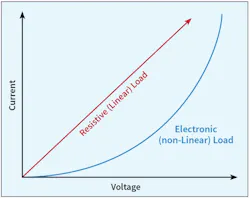
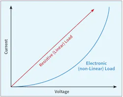
As end-users, we know that electronic loads have electronics — diodes, transistors, and integrated circuits — in them. But what is an electronic load graphically in terms of voltage and current? Figure 1 illustrates the behavior of current when the voltage applied to an electronic load is changed. Unlike a resistive load, the current in an electronic load does not change at a constant rate when the voltage is varied. When the voltage across an electronic load is changed, the current responds differently according to how much voltage is applied. In other words, the current responds at a different rate.
This non-linear action also affects the impedance of the source and circuit that must power the electronic load. Linear loads have a constant relationship between the voltage applied across the load and the current flowing through it. Prior to the invention of electronics, that constant impedance in all electrical systems was 50 ohms. Looking across the system — from the grid source into the building electrical system (BES) and into the load — the impedance used to be 50 ohms. However, this is no longer true. The use of electronic loads has made our systems much more complicated and difficult to predict regarding behavior.
As soon as the first electronic load was connected to the BES, the impedance of the system began to change. As additional electronic loads were plugged into the BES over the past five decades, the impedance continued to drift away from 50 ohms. In some cases, the impedance was less than 50 ohms; in others, it was greater than 50 ohms. Today, after years of research and testing, experts have found that the impedance ranges from about 0.1 ohms (500 times less) to as much as 100 ohms (two times more). The interesting questions surrounding these results are:
- What effects does this change in impedance have on the behavior of the grid?
- What effects does this change in impedance have on the behavior of the customer’s BES?
- What effects does this change in impedance have on the behavior of power quality (PQ) and electromagnetic interference (EMI) equipment?
This article addresses the third question. Whether we’re talking about the grid, the BES, or a device anywhere in between the grid, the BES and the load, the effects of a dynamically changing impedance are critically important to how the grid, the BES, and the device behave. The behavior of the electronic load governs how each behaves. What causes grid, BES, and load problems is that we don’t understand how the behavior of the load impacts the grid, the BES, and any mitigation device in between them.
The effects of electronic loads on EMI filters
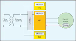
Figure 2 illustrates a typical setup in an industrial plant. An upstream power source (i.e., a dry-type step down transformer) powers one or more VFDs, an industrial power supply (IPS), and a programmable logic controller (PLC). Every electronic load incorporates an EMI filter inside of its housing. The purpose of an EMI filter is to “scoop off” enough of the high-frequency conducted noise (emissions) to lower the emissions that get back on the AC power line upstream of the load (VFD, IPS or PLC) to a level below some limit. The filter contains elements — resistors, capacitors, and inductors — that absorb most of the emissions and convert them into heat. Some of the emissions are routed through the equipment grounding conductor (EGC) that the elements are referenced to. The EGC then routes them into the BES’s EGC, which returns to the next upstream electrical panel.
With impedance being the relationship between the voltage and current, the impedance of any system governs the way the system and its loads respond to the electrical phenomena occurring within the system. In the non-electronic (linear) world, the impedance of the system is a constant 50 ohms, so the behavior of the system elements (the EMI filter being one of those elements) is predictable based on a 50-ohm line impedance philosophy. Early EMI filter designs stemmed from design concepts published in MIL-STD-220B used for designing filters for matched impedance communications systems. That design philosophy rolled over into subsequent EMI filter design and became the norm.
However, the nature of the electronic load having a variable (non-linear) impedance slowly degraded the performance of EMI filters. As more electronic loads were powered by customer BESs, the impedance of the system continued to be even more dynamic, thus changing constantly (between 0.1 and 100 ohms) and never settled on its historical 50-ohm value. This is because the current drawn by electronic loads is never constant.
The shape of the current versus voltage curve is not a straight line, it’s exponential. Moreover, the exponential shape can change based on parameters within the electronic load. Nowadays, with electronic loads everywhere, EMI filter performance is at its worst. In some applications, the EMI filters in an industrial setting or inside of a product like a VFD, IPS, or PLC never work. They never get the opportunity to lower the emissions levels generated by the product. This is because the filters never see a constant 50-ohm impedance, which was the basis for the filter design (using MIL-STD-220B). In fact, some filters have even been found to amplify conducted emissions. Whether the filter is inherently designed into the product or external to the product (Fig. 2), the problem is the same — filters are not reducing emissions low enough to prevent noise-related equipment problems from occurring.
Figure 2 also shows an example of an external EMI filter added to the upstream AC line of a large VFD application. External EMI filters are sometimes added to large VFD applications (typically larger than 100 horsepower). These filters are added in addition to the EMI filters inherent to the VFD’s internal design circuitry. This is one example that demonstrates the near ineffectiveness of EMI filters designed based on MIL-STD-220B.
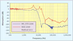
Figure 3 illustrates the difference in attenuation (dB) between a generic 50A EMI filter loaded by an electronic load drawing 30A. One can see from the graph that the filter’s performance is predicted to be much better when the MIL-STD-220A/B method is used versus when the more realistic IEEE 1560 (Method 10.5) method is used. The IEEE 1560 – Standards for Methods of Measurement of Radio Frequency Power Line Interference Filter in the Range of 100 Hz to 10 GHz, includes a series of tests designed to more realistically predict filter performance in the real world where electronic loads must live. At some frequencies, the difference in filter performance is a much as 120 dB — a very substantial difference in filtering capability. Application of IEEE 1560 will improve filter performance to the extent where noise-related equipment problems will essentially vanish over time.
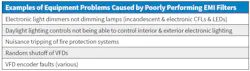
What happens when an EMI filter poorly performs (see the Table)? When the conducted emissions levels are left to increase to whatever levels they can reach, they are free to flow wherever they want to inside the application. In fact, they can be so high that they can flow into other electronic equipment powered by other BES circuits in a customer’s facility.
Figure 2 shows three other loads in addition to the large VFD. It shows an industrial power supply (IPS), a programmable logic controller (PLC), and a VFD-rated electric motor fitted with an electronic encoder. Encoders gather information about the application and send it to the VFD (and PLC), so the application can do its job. Information like speed, position, motor type, etc. can be gathered by encoders and sent to the VFD and/or PLC to make necessary adjustments to the process. However, when emissions levels are high, the encoder’s signals can be corrupted giving rise to encoder faults, which can shut down the industrial process. When these problems occur, industrial customers experience interruptions in their production processes, which typically equate to high financial losses.
Other system characteristics that impact EMI filter performance
Because the impedance of the system governs how EMI filters perform, there are other inherent impedance characteristics that will also influence EMI filter performance. These include grounding, source impedance, circuit and feeder impedance as well as harmonics (among others). Each one of these is critically important to how EMI filters perform. Engineers already know that grounding is one of the most critical parameters that affect almost every part of an electrical system. Grounding problems typically equate to higher impedance grounds which will not only make it more difficult for emissions to get out of the filter but can also impact the performance level of the filter, that is, how well the filter is able to reduce (or absorb) emissions.
The new objective in EMI filter design and performance is to ensure that the filter can provide the filtering required to reduce conducted emissions below levels promulgated by the U.S. Federal Communications Commission (FCC), International Electrotechnical Commission (IEC), and the Institute of Electrical and Electronics Engineers (IEEE) among other standards organizations, even when the impedance of the system varies across the wide range from 0.1 ohms to 100 ohms.
Anything that impacts the impedance (or negates the filter’s ability to compensate for changes in impedance) will impact the filter’s performance. Thus, long feeder and branch circuits that have a higher impedance than shorter ones will impact filter performance. In addition, a soft versus a stiff source will also impact filter performance. The impedance of a soft source will vary more than the impedance of a stiff source when the load current changes. Thus, filter performance will be better for sources with stiff impedances.
Designing EMI filters in varying electrical environments with the objective of maintaining filter performance when environments change is obviously a power quality (PQ) concept. Thus, anything that affects the quality of the voltage and current will also impact EMI filter performance.
One PQ phenomenon that PQ experts often study is harmonics. Harmonics are additional frequencies that are added to the voltage and current waveforms that will cause some level of harmonic distortion. The adage, “The voltage belongs to the electric utility, and the current belongs to the customer” is obviously true again here. The shape of the load current drawn by the electronic load will impact filter performance. Why? This is because the performance of the elements of an EMI filter —resistors, capacitors and inductors — can be impacted by harmonic current distortion. One of the new test methods in the IEEE 1560 is to determine the filter’s performance under harmonic current conditions. When the harmonic current is too high, the inductive elements inside a filter will become saturated; thus, essentially taking them out of the circuit and leaving the filter in a state where it cannot reduce conducted emissions. The same can be true for the voltage — if the voltage is too distorted, then the current drawn by the electronic load can be even more distorted and increase the likelihood of the filter not being able to perform.
What to do about the problem
Some experts in the field of PQ and EMI have the capability to identify EMI filters in an application that are not performing. Specific tests can be carried out in the field to measure conducted emissions as well as PQ parameters to determine a filter’s performance. New filter design methods can be implemented to design new EMI filters that can not only reduce the level of conducted emissions but minimize them across all of the operating conditions of the industrial application. Yes, improved EMI filter performance costs more money, but the return of investment (ROI) is much better given, that industrial and commercial customers don’t have to ensure the financial burdens of experiencing equipment shutdowns caused by poor EMI filter performance.