Ground Planes for LED Drivers — Part 3 of 3
In Part 1 of this three-part series, we discussed the importance of a well-engineered PCB ground plane for LED drivers, so the ground plane can be effective in managing disturbance energy generated internal and external to the driver. In Part 2, we examined the basic grounding deficiencies in electrical panels, which increase the likelihood of facility-generated disturbances that cause damage to LED drivers on lighting branch circuits. In this third and final part, we’ll look at how advanced power quality (PQ) monitoring can be used to identify disturbances that cause premature failures of LED drivers installed in luminaires.
Aside from knowing how to read and interpret PQ monitoring data, the biggest mistake one makes during a PQ investigation is selecting the most appropriate location to monitor. One must realize the PQ monitors are not simple digital voltmeters (DVMs). PQ monitors are sophisticated instruments designed to record detailed information regarding the voltage and current occurring at the monitoring point and graph that information with respect to time and frequency. Good PQ monitors do more than graph voltage and current trends against time and frequency. Humans like to see images, especially when trying to analyze and solve a problem. Therefore, being able to view and dissect waveforms of voltage and current disturbances is valuable when trying to determine where disturbances are coming from and how they get to electronic equipment.
Because wires and metals are not perfect conductors — and all electrical systems require hundreds of mechanical connections that allow a facility power system and its loads to function properly — one PQ monitoring point will behave differently than an upstream or downstream monitoring point. Consider the simplified diagram of three PQ monitoring points shown in Fig. 1.
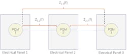
Electrical conductors — power, neutrals and grounds (insulated and uninsulated), electrical panels and their mechanical connections required to keep the system together electrically / mechanically — have inherent parasitics (distributed resistance, capacitance and inductance that influence the characteristics of the voltages and currents facility power systems must support). Electrical conductors also behave differently with respect to frequency when installed in metals conduits and raceway than they do when they are suspended in open air, for example. Moreover, mechanical connections aren’t perfect either. They vibrate at 60 Hz/sec with most connections designed to be reversed (loosened) for maintenance, repair, and modification. The impedances — Z1-2(f), Z2-3(f) and Z1-3(f) — shown in Fig. 1 include the effects of the conductors (power, neutrals, and ground), panels, and connections. Each impedance has a resistive, capacitive, and inductive element. Each impedance is different in terms of its frequency response and its ability to maintain “stable” power flow. In traditional, older electrical environments, the frequency characteristics of the current was almost all at the 60-Hz level. Moreover, few, if any, electronic equipment was installed in customer facilities. So, when a transient was generated by the operation of a circuit breaker (especially the large ones) — the operation of a contactor by the electric utility during normal operations — there was no electronic equipment to malfunction or fail. Even transients (surges) generated by electrical storms wouldn’t cause detrimental effects to electronic equipment — because there was none.
However, today’s customer environments are drastically different. All the above now has the likelihood of causing malfunction and damage to electronic equipment. Moreover, a disturbance generated by one piece of electronic equipment or a circuit breaker/contactor becomes a real threat to another piece of electronic equipment. A piece of electronic equipment doesn’t have to be installed on the same circuit, panel, or even in the same building to have an unmanaged risk of being damaged by disturbances.
Because disturbances generated by electronic equipment, facility operations and grid operations cause complex disturbance currents to flow, the three impedances shown in Fig. 1 will react differently to each disturbance. The reaction depends on many factors. Knowing these factors and their dependencies is where the PQ engineering experience and expertise becomes valuable.
The initial knowledge that many gained when taught about PQ monitors and monitoring seemed to have guided us to always install a monitor at the service entrance — near or at the point-of-common-coupling (POCC). Although installing a monitor at this point will provide some very good data, we are only “scratching the surface” when it comes to determining the source of disturbances and how they can make it to electronic equipment to cause damage.
One must engage in monitoring deeper into the facility power system to unravel the PQ mystery. Why? Remember the old rule of thumb — 70% to 80% of all PQ problems are caused by the customer’s electrical environment and the equipment installed there. Common sense tells us we can’t expect to determine the cause of the problem if we only monitor at the service entrance (POCC). We must get into the customer’s facility to understand disturbance sources, paths, failure mechanisms, and exposure of electronic equipment to disturbances.
Lighting systems are unique and must be studied much differently than when PQ investigations are conducted regarding malfunctions and failures of other electronic loads. The uniqueness of lighting systems adds more variables to the puzzle, which we must deal with when trying to determine why LED drivers, for example, are malfunctioning and failing. Why is this? Well, the equipment grounding conductors (EGCs) of luminaires must be bonded to facility ground. This is accomplished by ensuring the EGC is bonded to the ground conductor of the lighting branch circuit. However, sometimes that ground conductor in the branch circuit is missing. In many cases, rather than pulling new lighting branch circuit conductors, some installers will allow the EGC to be bonded to the metal of the luminaire.
However, no bonded ground is typically installed directly between the EGC and the metal roof or steel beams of the building. Installers will many times make up a locking receptacle — male end on the fixture side, and female end on the building side with the grounding conductor in the female locking receptacle bonded to a metal junction box physically attached to a piece of metal channel, building steel or a threaded rod (or chain) attached to a beam clamp, which is bonded to building steel. In these cases, the grounding conductor on the building side is likely to have an unacceptable impedance, especially when disturbance currents generated by the driver’s electronic power supply try to flow back to earth ground.
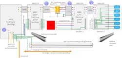
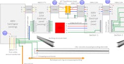
Referring to Fig. 2, there are likely other disturbance-generating loads such as variable-frequency drives (VFDs), electronic battery chargers, industrial power supplies, and other power electronic-based equipment installed in the 480V/277V panels as well as in the 208V/120V panels. Because disturbance-generating loads and wiring/grounding errors can be found anywhere within a facility power system, one must be strategic when determining the location for PQ monitoring. The purple circles with “PQM 1,” “PQM 2,” etc. in Fig. 2, show some possible locations for installing monitors. One should start with two monitors with one placed on a lighting branch circuit where malfunctioning/failing LED drivers have occurred. A possible monitor location includes the direct mounting location where a luminaire is installed. Correlation between monitoring setups and monitoring data is required to provide one with enough information to determine where disturbance sources and wiring/grounding errors are located, which might be contributing/causing LED driver failures. Expect there to be more than one problem-causing disturbance source and many wiring/ground errors.
The Photo shows a 225A, 480V electrical panel (Section 1 in Fig. 2) downstream of the switchgear that also powers two VFDs at 480V. Note that these panels are grounded via their rigid conduits from the switchgear with no dedicated ground conductor. There is a second part (Section 2 in Fig. 2) to this panel, which is bonded to Section 1 via a short section of rigid pipe with locknuts. Rigid is much better than electrical metallic tubing (EMT), which has at least one EMT coupling every 10 ft. However, rigid pipe relies on threads that fit together with rigid couplings, etc. Over time, pipe threads rust due to moisture seeping into the threads. Many pipe threads have heavy oil residues left from threading which also act as barriers to good electrical connections to help establish low impedance connections between sections of pipe.
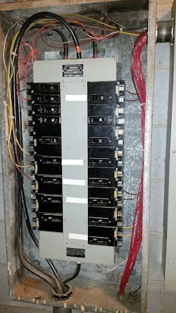
Also note there are no EGCs running to individual lighting branch circuits. Moreover, there is no grounding bar bonded to the panel. There are a mix of rigid pipes and EMT, leaving this panel to 4-in. junction boxes mounted on the ceiling and to lighting control panels. These missing EGCs add to the unmanaged risks of known electrical disturbances (i.e., voltage transients) occurring in this commercial facility, which were shown to cause permanent damage to electronic LED drivers mounted in fixtures more than 100-ft up on the ceiling.
The unmanaged risks are many, and the likelihood of driver failures needs attention. Hindsight shows us that the costs of proactive monitoring before LED lighting is installed is much less than the cost of cleaning up these problems after the fact. A recommended monitoring period of at least a week at different panel locations will provide limited but somewhat informative data, revealing the disturbances occurring on these panels. Two to three weeks of monitoring helps to capture disturbances from cyclical loads. Dedicated grounds to these panels and EGCs to each lighting branch circuit will help reduce the unmanaged risks of damaging new electronic LED drivers from disturbances caused by electronic switching in VFDs and from power system-level switching as well.
Keebler is a senior power quality engineer and power systems consultant at Electrotek Concepts, Inc. in Knoxville, Tenn. He can be reached at [email protected].
About the Author
Philip Keebler
Senior Power Quality Engineer
Philip F. Keebler, MSEE has 32 years of experience in power quality (PQ) having worked for North American Philips, Electric Power Research Institute (EPRI), Electrotek Concepts & Dranetz. His experience spans across the utility revenue meter addressing PQ problems on the grid and inside residential, commercial and industrial customer facilities. His specialty areas include grounding, disturbances, harmonics, electromagnetic interference (EMI), equipment immunity, PQ monitoring, training and standards development. He serves as a Technical Advisor to PBE Engineers, LLC focused on understanding, identifying, solving and preventing (UISP) PQ problems in the industry and fostering new interest and workforce development to attract young engineers to developing careers in PQ. He can be reached at [email protected].