Harmonics: Identification and Diagnosis Detailed
In last month’s column, I addressed the question of what harmonics is and why you should care. In this installment of our multi-part series on power quality topics, we’ll move on to how to identify, monitor, diagnose, and deal with harmonics in electrical power systems.
Harmonics are currents or voltages with frequencies that are integer multiples of the fundamental power frequency, which is 60 Hertz in the United States. When waveforms deviate from a pure sinewave shape, they contain harmonics.
Harmonics can have several negative effects on power systems, including:
- Increased voltage drop and power loss in conductors
- Overheating of equipment and conductors
- Misfiring in variable-speed drives
- Torque pulsations in motors and generators
- Interference with communication and control systems
- Flickering lights
- Noise
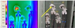
So, if you identify any issues like those listed above, how would you go about determining if it is harmonics related as opposed to another cause (such as a loose connection, equipment short, or other various possibilities)? We typically recommend that simpler diagnostics are performed first. This would include visual inspection, cleaning, and torquing of connections. These are detailed in at least two industry standards:
- ANSI/NETA-MTS Standard for Maintenance Testing Specifications for Electrical Power Equipment and Systems, and
- NFPA-70B, Standard for Electrical Equipment Maintenance.
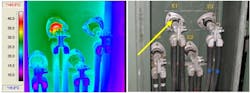
With the basic inspections and testing conducted — and being no closer to determining a cause of the negative issue being experienced on a single piece of equipment or an entire power system — it would be appropriate, if suspected, to look at harmonics as a possible cause.
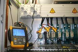
The most effective way to determine and quantify the presence of harmonics (and to what degree) is to install a portable power quality analyzer (PQA) at the location of the suspected problem. Many reputable PQAs on the market can record current and voltage harmonics hundreds of times the fundamental frequencies. These PQAs can be set up to record for days, weeks, or months, and they can capture harmonic data and calculate current and voltage total harmonic distortion (THD). A typical portable PQA installation setup is shown in Photo 2.
Given the large number of non-linear loads present on our power systems (as discussed previously), there is always some distortion of the fundamental waveform from the utility to the customer’s facility, and thus some amount of harmonics exist.
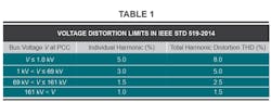
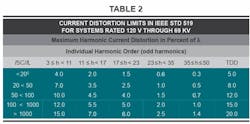
Several standards dictate an acceptable THD that should be present, as levels above this can cause uneven heating or other negative effects on electrical equipment. The main guide is IEEE Std 519, Recommended Practice and Requirements for Harmonic Control in Electrical Power Systems.
Recommended harmonic limits are found in Section 5 of the IEEE 519 standard and are shown in Tables 1 and 2.
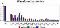
We expect to see off-fundamental voltages and currents in the odd harmonics (3rd, 5th, 7th, etc.) in greater quantities. A typical harmonic spectrum output may resemble what’s shown in the Figure below.
David Colombo, P.E. is a professional engineer located in Massachusetts, and the owner and principal of Power Engineers, LLC, a design, engineering, and consulting firm. He has more than 30 years in the electrical engineering and construction industry and is involved with the design of utility substation & distribution infrastructure, large-scale renewable energy projects, and commercial / industrial power systems. He specializes in the areas of medium-voltage design, power distribution, protection, metering, power quality, power studies, and arc flash analysis. He also provides owner’s engineering support for developers, EPC contractors, and project owners. Prior to starting Power Engineers, LLC and being an engineering consultant, he was a utility distribution supervising engineer. He holds a bachelor of science degree in electrical engineering from Worcester Polytechnic Institute (WPI) and a master of engineering degree in electric power engineering from Rensselaer Polytechnic Institute (RPI). He is a registered professional engineer in 13 states.
About the Author

David Colombo
David Colombo, P.E. is a Professional Engineer located in Massachusetts, and the owner and principal of Power Engineers, LLC, a design, engineering and consulting firm. He has over 30 years in the electrical engineering and construction industry and is involved with the design of utility substation & distribution infrastructure, large scale renewable energy projects, and commercial / industrial power systems. He specializes in the areas of medium-voltage design, power distribution, protection, metering, power quality, power studies and, arc flash analysis. He also provides owner’s engineering support for developers, EPC contractors and project owners. Prior to starting Power Engineers, LLC and being an engineering consultant, he was a utility distribution supervising engineer. He holds a Bachelor of Science degree in Electrical Engineering from Worcester Polytechnic Institute (WPI) and a Master of Engineering degree in Electric Power Engineering from Rensselaer Polytechnic Institute (RPI). He is a Registered Professional Engineer in 13 states.