All questions and answers are based on the 2011 NEC.
Q. What kind of marking does the Code require to identify the high-leg of a 3-phase, 4-wire delta connected system?
A. On a 4-wire, delta-connected, 3-phase system, where the midpoint of one phase winding of the secondary is grounded (a high-leg system), the conductor with 208V to ground must be durably and permanently marked by an outer finish orange in color or other effective means [110.15]. Such identification must be placed at each point on the system where a connection is made if the neutral conductor is present [230.56].
The high-leg conductor is also called the “wild leg,” “stinger leg,” or “bastard leg.” Other important NEC rules relating to the high leg are as follows:
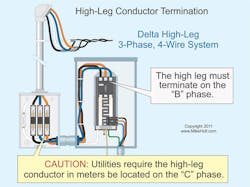
Panelboards — Since 1975, panelboards supplied by a 4-wire, delta-connected, 3-phase system must have the high-leg conductor terminate to the “B” phase of a panelboard [408.3(E)]. Section 408.3(F)(1) requires panelboards to be field-marked with “Caution: Phase B Has 208V to Ground.”
Disconnects — The NEC doesn’t specify the termination location for the high-leg conductor in switch equipment (Art. 404), but the generally accepted practice is to terminate this conductor to the “B” phase.
Utility equipment — The ANSI standard for meter equipment requires the high-leg conductor (208V to neutral) to terminate on the “C” (right) phase of the meter socket enclosure. This is because the demand meter needs 120V, and it obtains that voltage from the “B” phase, as shown in Fig. 1. Also hope the electric utility lineman isn’t color blind and doesn’t inadvertently cross the “orange” high-leg conductor (208V) with the red (120V) service conductor at the weatherhead — it’s happened before.
Warning: When replacing equipment in existing facilities that contain a high-leg conductor, care must be taken to ensure the high-leg conductor is replaced in its original location. Prior to 1975, the high-leg conductor was required to terminate on the “C” phase of panelboards and switchboards. Failure to re-terminate the high leg in accordance with the existing installation can result in 120V circuits being inadvertently connected to the 208V high leg, with disastrous results.
Q. What is the NEC rule regarding objectionable current?
A. To prevent a fire, electric shock, or improper operation of circuit overcurrent devices or electronic equipment, electrical systems and equipment must be installed in a manner that prevents objectionable neutral current from flowing on metal parts [250.6]. Temporary currents from abnormal conditions, such as ground faults, aren’t classified as objectionable current [250.6(C)]. In addition, currents that introduce noise or data errors in electronic equipment are not considered objectionable currents for the purposes of this section. Circuits that supply electronic equipment must be connected to an equipment grounding conductor [250.6(D)].
Objectionable neutral current occurs because of improper neutral-to-case connections or wiring errors that violate 250.142(B).
Improper neutral-to-case connection [250.142].
Panelboards. Objectionable neutral current will flow when the neutral conductor is connected to the metal case of a panelboard that’s not used as service equipment.
Separately derived systems. Objectionable neutral current will flow on conductive metal parts and conductors if the neutral conductor is connected to the circuit equipment grounding conductor on the load side of the system bonding jumper for a separately derived system.
Disconnects. Objectionable neutral current will flow when the neutral conductor is connected to the metal case of a disconnecting means that’s not part of the service equipment.
Wiring errors. Objectionable neutral current will flow when the neutral conductor from one system is connected to a circuit of a different system.
Objectionable neutral current will flow on metal parts when the circuit equipment grounding conductor is used as a neutral conductor such as where:
• A 230V time-clock motor is replaced with a 115V time-clock motor, and the circuit equipment grounding conductor is used for neutral return current.
• A 115V water filter is wired to a 240V well-pump motor circuit, and the circuit equipment grounding conductor is used for neutral return current.
• The circuit equipment grounding conductor is used for neutral return current.
Dangers of objectionable current. Objectionable neutral current on metal parts can cause electric shock, fires, and improper operation of electronic equipment and overcurrent devices, such as GFPs, GFCIs, and AFCIs.
Shock hazard. When objectionable neutral current flows on metal parts, electric shock — and even death — can occur from the elevated voltage on those metal parts.
Fire hazard. When objectionable neutral current flows on metal parts, a fire can ignite adjacent combustible material. Heat is generated whenever current flows, particularly over high-resistance parts. In addition, arcing at loose connections is especially dangerous in areas containing easily ignitable and explosive gases, vapors, or dust.
Improper operation of electronic equipment. Objectionable neutral current flowing on metal parts of electrical equipment and building parts can cause electromagnetic fields that negatively affect the performance of electronic devices, particularly medical equipment.
Operation of overcurrent devices. When objectionable neutral current travels on metal parts, tripping of electronic overcurrent devices equipped with ground fault protection can occur because some neutral current flows on the circuit equipment grounding conductor instead of the neutral conductor.
Q. Does the NEC allow the use of trees to support overhead feeder or branch circuit conductors?
A. Trees or other vegetation must not be used for the support of overhead conductor spans. This applies to both feeders and branch circuits [225.26]. Section 410.36(G) does allow trees to be used for the support of luminaires, as shown in Fig. 2.
Service-drop conductors installed by the electric utility must comply with the rules of the National Electrical Safety Code (NESC), not the National Electrical Code [90.2(B)(5)]. Overhead service conductors that aren’t under the exclusive control of the electric utility must be installed in accordance with the NEC.
Q. What is the NEC rule regarding labeling of electrical service equipment with the maximum available fault current?
A. Service equipment in other than dwelling units must be legibly field-marked with the maximum available fault current, including the date the fault current calculation was performed and be of sufficient durability to withstand the environment involved [110.24(A)]. When modifications to the electrical installation affect the maximum available fault current at the service, the maximum available fault current must be recalculated to ensure the service equipment ratings are sufficient for the maximum available fault current at the line terminals of the equipment. The required field marking(s) in 110.24(A) must be adjusted to reflect the new level of maximum available fault current [110.24(B)].
Exception: Field markings aren’t required for industrial installations where conditions of maintenance and supervision ensure that only qualified persons service the equipment.
Q. What is the Code rule for overcurrent protection of feeder conductors?
A. Feeder overcurrent devices must have a rating of not less than 125% of the continuous loads, plus 100% of the noncontinuous loads [215.3]. See 215.2(A)(1) for feeder conductor sizing requirements.
Exception: If the assembly and the overcurrent device are both listed for operation at 100% of its rating, the overcurrent device can be sized at 100% of the continuous load.
Equipment suitable for 100% continuous loading is rarely available in ratings under 400A.
About the Author

Mike Holt
Mike Holt is the owner of Mike Holt Enterprises (www.MikeHolt.com), one of the largest electrical publishers in the United States. He earned a master's degree in the Business Administration Program (MBA) from the University of Miami. He earned his reputation as a National Electrical Code (NEC) expert by working his way up through the electrical trade. Formally a construction editor for two different trade publications, Mike started his career as an apprentice electrician and eventually became a master electrician, an electrical inspector, a contractor, and an educator. Mike has taught more than 1,000 classes on 30 different electrical-related subjects — ranging from alarm installations to exam preparation and voltage drop calculations. He continues to produce seminars, videos, books, and online training for the trade as well as contribute monthly Code content to EC&M magazine.


