Avoiding Common NEC Violations on Solar PV and BESS Projects
Key Takeaways
- Proper sizing of conductors and protective devices according to NEC Sections 690.7 and 690.8 is essential for system safety and compliance.
- Effective grounding and bonding, especially for PV modules and associated equipment, are critical to prevent shock hazards and meet NEC requirements.
- Understanding the differences between Articles 480 and 706 helps in correctly applying safety standards for traditional standby batteries versus active energy storage systems.
- Implementing fire mitigation measures such as ventilation, fire suppression, and thermal management reduces the risk of thermal runaway and fire hazards in BESS installations.

With solar photovoltaic (PV) and battery energy storage systems (BESSs) becoming increasingly common in today’s electrical infrastructure, ensuring compliance with NFPA 70, the National Electrical Code (NEC), remains a critical priority for designers, contractors, and inspectors.
This article highlights and offers preventive guidance for common NEC violations. It covers Sec. 690.7 and Sec. 690.8 for maximum circuit voltage and current, Sec. 690.43 for grounding and bonding of solar array equipment, and makes distinctions between Art. 480 and Art. 706 as they apply to stationary standby batteries versus energy storage systems. This article also outlines best practices for fire hazard mitigation, ventilation, and ongoing maintenance of BESS installations — practices that reduce risk, improve reliability, and build client confidence.
Solar PV systems
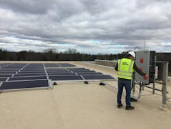
Photovoltaic (PV) systems are becoming a more common component of both small-scale and electric utility power generation assets; therefore, safe installation and compliance with the NEC are critical to ensuring reliable and long-lasting performance. Article 690 addresses conductors, overcurrent protection, disconnecting means, grounding, bonding, and labeling for PV systems. A PV system comprises a series of components that work together to produce usable electricity from sunlight. The PV modules convert sunlight into DC power, conductors in raceways carry that current to inverters, and the inverters create usable AC power for distribution. Overcurrent protection, disconnects, and grounding equipment are then applied to safeguard both people and equipment. Each component must be properly sized and installed in accordance with the tables and calculations provided in Art. 690 (Photo 1).
In PV system design, the calculations for circuit voltage and current must be precise and ensure both safety and compliance with the NEC. Section 690.7 and Sec. 690.8 address these requirements and establish a clear method for sizing equipment, conductors, and protective devices, thereby accounting for environmental and operating conditions applicable to each unique installation.
Section 609.7 outlines requirements for determining the maximum voltage in PV source and output circuits. Section 690.7(A) outlines the process for determining the maximum circuit voltage for the system — calculating the open-circuit voltages of the modules in series. Refer to Table 670.7(A) to account for the lowest ambient temperature for the installation; this provides calculated correction factors because the PV modules will produce higher voltages under cooler temperatures.
Information about a location’s historical weather and temperature can be obtained through the National Oceanic and Atmospheric Administration (NOAA). Using NOAA’s data, an engineer can determine the lowest temperature that an installation is likely to experience and, thereby, apply an accurate correction factor. Applying the correction factor to the series sum determines the highest voltage, within reason, that the system may produce. After this value has been obtained, one must ensure all equipment — including disconnects, overcurrent protection, inverters, and conductors — is rated to withstand the maximum expected voltages.
Furthermore, Sec. 690.7 limits the PV system’s maximum voltage, depending on the type of installation (e.g., a maximum of 600V for dwelling installations, 1,000V for non-dwelling, and up to 1,500V for utility-scale systems). These limitations ensure the components are within their design ratings, thus preventing insulation breakdown, arcing, or other failures induced by overvoltage incidents.
Section 690.8 provides the framework for determining the circuit currents of the PV system; doing so ensures proper conductor and overcurrent protection. Section 690.8(A) requires the maximum circuit current to be calculated with the rated short-circuit current (Isc) of the modules. That number is then multiplied by 125% to account for irradiance and operating conditions. For the PV source circuit (point at which the PV module connects to the protection device), this value is the sum of the paralleled modules’ Isc ratings entire PV output. Section 690.8(B)(1) then requires that both conductors and overcurrent protection devices be sized to at least 125% of these maximum currents, effectively applying a 156% factor between module Isc and conductor ampacity. Inverter output circuits are sized differently based on the name plates’ continuous output; also, systems with multiple inverters or storage must coordinate with Art. 705. These requirements ensure that wiring and protection are not undersized, thus reducing the risk of overheating or fire during continuous maximum exposure.
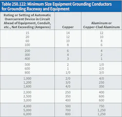
In solar PV installations, improper grounding of racking, module frames, and associated equipment remains one of the most frequent Code violations. Section 690.43 requires exposed metal parts of PV module frames, electrical equipment, and conductor enclosures to be effectively grounded and bonded (in accordance with Sec. 250.134 or Sec. 250.136, regardless of voltage) to ensure a continuous low-impedance fault current path. In the field, however, equipment grounding conductors (EGCs) are often undersized or omitted, and continuity testing between modules is sometimes skipped during commissioning. These oversights not only violate Code requirements but also create serious safety hazards by increasing the risk of shock or fire. To reinforce proper sizing of EGCs, Sec. 690.45 further requires EGCs to be sized in accordance with Sec. 250.122 and Table 250.122. When a protective device does not exist within the circuit, Table 250.122 (below) may still be applied using an assumed overcurrent device rating, as permitted by Sec. 690.9(B), to ensure proper conductor sizing.
BESS
BESS use continues to grow alongside solar PV, and safe integration into electrical infrastructure has become a priority within the NEC and across industry practices. A BESS is an integrated system composed of battery modules, a power conversion system (PCS), thermal management, safety controls, and more, all working together to store energy and distribute it to the electrical system when needed. Importantly, a BESS should not be confused with what is traditionally thought of as a stationary standby battery; rather, it is a coordinated system of electrical, electrochemical, and mechanical components designed for large-scale energy storage and delivery.
The NEC distinguishes between different types of battery installations. Articles 480 and 706 both pertain to battery systems, but the application and requirements are different. Article 480 applies to traditional stationary battery systems that are to be used for emergency or standby power. These are legacy-style installations, using lead-acid battery banks to support emergency lighting, switchgear control, or an uninterrupted power supply system. These systems are designed to stay fully charged and only discharge when there is a loss of power. Because of the nature of these systems, the batteries are rarely cycled. The NEC views these systems as a fixed safety measure, focusing mostly on ventilation, disconnection means, overcurrent protection, and hazard signage. Article 480 treats the battery pack as a backup supply, not as an active energy source.
By contrast, Art. 706 was introduced to support the rise of BESS, which differs from standby banks in both technology and function. These systems use lithium-ion and other advanced chemical batteries designed for large numbers of charge and discharge cycles. Article 706 includes provisions for the power management systems, thermal runaway protection, system controls, and utility interconnection integration. The Article outlines system-level controls to ensure proper charging, discharging, and coordination with other power sources. Article 706 also includes details regarding how BESS integrates multiple alternative energy courses (such as solar and wind) into one power system. In 2023, the NEC expanded Art. 706 with further guidance and informational notes, emphasizing its role in regulating actively managed energy storage that participates in the day-to-day operation of electrical systems.
To conclude, Art. 480 continues to cover conventional backup battery systems that sit idle until needed, whereas Art. 706 addresses dynamic energy storage technologies that operate as part of everyday energy use. Understanding the difference is crucial to applying the correct Code requirements in the ever-changing and rapid advancement of alternative energy generation and storage.
One of the leading concerns for many clients is the fire hazards associated with a BESS. Section 706.5 of the NEC requires energy storage systems (ESSs) to be listed; two of the most common listings used in the industry are Underwriters Laboratories (UL) 9540 and UL 9540A. UL 9540, the standard for ESS and equipment, evaluates overall product safety by addressing electrical, mechanical, environmental, and functional performance. It also considers component compatibility, operation and maintenance, and integration with the electrical grid. UL 9540A, by contrast, is a test method that examines how an ESS behaves under thermal runaway conditions, including the potential for fire propagation and gas release. Together, these listings provide critical safety data and assurance for authorities having jurisdiction and are highly recommended for use in BESS installations.
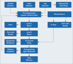
While NEC requirements and UL listings establish a strong safety foundation for fire mitigation, applying industry best practices adds an extra layer of protection and client reassurance. To address these concerns, many manufacturers equip their BESS enclosures with fire suppression systems, enhanced ventilation, and additional cooling features. Fire suppression systems typically integrate three detectors (smoke, gas, and heat) that feed data to a central control panel. Based on this input, the system can automatically activate exhaust fans, trigger alarms with horn and strobe signals, and release extinguishing agents. The Figure belowshows an example of a fire suppression system flowchart.
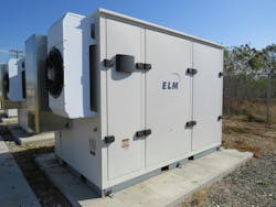
Section 706.20 requires ventilation for an ESS to be provided in accordance with the manufacturer’s recommendations and the system’s listing, leaving minimum requirements open to interpretation based on the specific equipment. It is therefore important to confirm with manufacturers that their base-level ventilation can sufficiently prevent the accumulation of explosive gases within BESS enclosures. As shown in Photo 2, sufficient ventilation serves as a key safeguard, typically provided through exhaust fans that often work in tandem with air-conditioning units to maintain consistent air circulation and temperature control.
Additional cooling measures further reduce the risk of overheating and thermal runaway. In most manufacturers’ designs, air-conditioning regulates the temperature of the power control system (PCS), while self-contained liquid cooling systems manage the thermal demands of the battery cabinets. If the cooling systems are unable to maintain safe battery temperatures, then best practices call for equipping the BESS with over-temperature sensors that can shut down the system to prevent fires and thermal runaway.
Another leading concern for many clients is ensuring the long-term maintenance and reliable operation of BESS installations. Routine inspection and upkeep are critical for identifying potential issues before they escalate into safety or performance problems. While manufacturers provide maintenance checklists and guidance, it is important to consistently adhere to these schedules. Delaying or skipping scheduled maintenance can increase the risk of system failures, reduce operational efficiency, and compromise safety. Common maintenance practices include regularly checking system connections, monitoring battery performance and temperature, cleaning components as needed, and promptly replacing worn or damaged parts. To help ensure these tasks are carried out properly, many clients find it beneficial to establish a service agreement with manufacturers, local dealers, or certified service providers.
Conclusion
Staying aligned with the NEC is critical as solar PV and BESS systems become more common. Understanding key sections — such as Sec. 690.7 and Sec. 690.8 for circuit sizing, Sec. 690.43 for grounding and bonding, and the noted distinctions between Art. 480 and Art. 706 — helps avoid common violations. Combined with best practices for fire hazard mitigation, ventilation, and maintenance, these measures ensure safe, reliable installations and offer clients confidence in their energy systems.
About the Author

Josh Bristow
Josh Bristow is an electrical engineering consultant for CDM Smith. He specializes in water/wastewater on-site consulting and power distribution.

Matthew Smith
Matthew Smith, EIT, is an electrical engineer with CDM Smith. He specializes in water/wastewater design and renewable systems.