Why Do You Need an Incident Energy/Arc Flash Analysis?

Protecting workers’ lives is a priority. If a serious incident occurs, the emotional and financial effects can be devastating. For most countries, including the United States, electrical safety is mandated and regulated by the law. OSHA 1910.132 requires employers to assess the workplace to determine if hazards are or are likely to be present. OSHA references the National Electrical Code (NEC), NFPA 70E – Standard for Electrical Safety in the Workplace, and IEEE standards for compliance. Additionally, these standards, as well as the National Electrical Safety Code (NESC), which is specifically enforced for electric utilities, require an arc flash assessment to be performed. IEEE 1584 – Guide for Performing Arc Flash Hazard Calculations, provides a procedure for performing the arc flash hazard/incident energy calculations.
What Causes an Arc Flash Event?
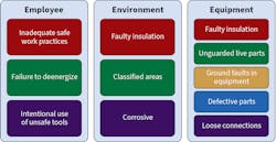
An arc flash is a rapid release of energy due to an electrical arcing fault. This could be due to a fault that is phase-to-phase, phase-to-ground, or phase-to-neutral. Sometimes, a worker can cause an arc flash by using inadequate safety practices, working on energized equipment, or intentionally using unsafe tools. For example, while working on energized equipment, a worker drops an uninsulated tool in the equipment that causes a phase-to-phase or phase-to-ground fault that escalates into an arc flash event.
Other things that may increase the risk of an arc flash event are related to the environment, such as moisture building up on the energized equipment, which can increase the conductivity and cause an arc. Faulty equipment that isn’t working properly, is defective, or allows exposure to foreign objects can also pose an arc flash risk. As Fig. 1 shows, when you start to combine these individual risks, you increase the chances of an arc flash event.
In addition, maintenance of electrical equipment is crucial because the risk of an arc flash occurring or equipment having exposed energized conductors or circuit parts can be dramatically reduced by adhering to sound maintenance practices and procedures.
Non-Compliance
A common occurrence that can happen relating to non-compliance is the misuse of personal protective equipment (PPE) tables contained in NFPA 70E. Something often overlooked is that NFPA 70E requires the available fault current and clearing time of the protective devices to be known, which typically isn’t the case. Furthermore, NFPA 70E states that an incident energy analysis must be performed for the following conditions:
• The worker’s task(s) are not listed in the tables.
• Power systems with greater than the estimated maximum available fault current.
• Power systems with longer than the maximum clearing times.
• Tasks with less than the minimum working distance.
When the NFPA 70E tables are used instead of an incident energy analysis, some things to consider include:
• Notes in the tables that have specific requirements for the PPE are generally ignored.
• The short-circuit current is assumed.
• The protective device clearing time is assumed.
In addition, maintenance of the protective devices is not considered when the tables are used. This can affect the incident energy in the event a sticky breaker or other protective device isn’t opening when it should, so the clearing time of the device would be inaccurate. It’s also important to note that the tables and the arc flash calculations are not intended to work together. Therefore, NFPA 70E did away with the PPE values and identifies PPE with actual incident energy values for the analysis.
Insufficient training can also be a problem because workers need to know the correct use of PPE, they need to be able to recognize electrical hazards, and they need to understand safe work practices. This training is required and specified by OSHA, NFPA 70E, and the NEC.
Inadequate Equipment Maintenance
For the arc flash hazard analysis to be valid, Sec. 130.5 in NFPA 70E requires the consideration of maintenance. As a case example, consider the following situation:
• A low-voltage power circuit breaker has not been operated or maintained for several years.
• The lubrication has become sticky or hardened.
• The circuit breaker could take additional time to clear a fault condition.
Two flash hazard analyses will be performed using a 20,000A short circuit with the worker 18 in. from the arc:
• Based on what the system is supposed to do [0.083 sec (5 cycles)].
• Due to a sticky mechanism, the breaker now has an unintentional time delay of 0.5 sec (30 cycles).
EMB = maximum 20-in. cubic box incident energy, cal/cm2
DB = distance from arc electrodes, inches (for distances 18 in. and greater)
tA = arc duration (seconds)
F = short circuit current, kA (for the range of 16kA to 50kA)
All calculations are based on formulas in NFPA 70E-2018, Annex D (D.3.3).
(1) DB = 18 in.
(2) tA = 0.083 sec (5 cycles)
(3) F = 20kA
EMB = 1038.7DB-1.4738tA × [0.0093F2 - 0.3453F + 5.9675]
EMB = 1038.7 × 0.0141 × 0.083 [0.0093 × 400 - 0.3453 × 20 + 5.9675]
EMB = 1.4636 × [2.7815]
EMB = 3.5 cal/cm2
Per Sec. 130.5 of NFPA 70E, arc-rated FR clothing and other PPE to be selected based on this incident energy level exposure. Thus, the FR clothing and PPE must have an arc rating of at least 3.5 cal/cm2.
Now, let’s run through the same calculation considering the sticky breaker scenario:
(1) DB = 18 in.
(2) tA = 0.5 sec (30 cycles)
(3) F = 20kA
EMB = 1038.7DB-1.4738tA × [0.0093F2 - 0.3453F + 5.9675]
EMB = 1038.7 × 0.0141 × 0.05 [0.0093 × 400 - 0.3453 × 20 + 5.9675]
EMB = 7.3179 × [2.7815]
EMB = 20.4 cal/cm2
Therefore, the FR clothing and PPE must have an arc rating of at least 20.4 cal/cm2.
Arc Flash Labels
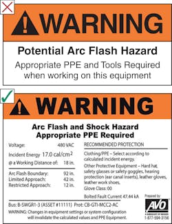
It’s important to use proper signage on electrical equipment, and that workers know the proper PPE to wear before beginning work on energized electrical equipment. The label shown in Fig. 2 with an “X” beside it is a generic arc flash label that does not inform the worker of the incident energy present at the equipment, the arc flash boundary, or even what type of PPE is required. The label with a check mark beside it is a typical arc flash label that is based on the requirements in NFPA 70E, Sec. 130.5. The detailed label shows the voltage, incident energy value, the working distance, and the arc flash boundary.
Also notice that the Limited Approach and Restricted Approach boundaries are shown. The limited approach boundary represents that a shock hazard exists within this boundary. The restricted approach boundary represents an increased shock hazard due to the electric arc over combined with inadvertent movement.
What is an Incident Energy Analysis?
Now that we know an arc flash hazard or incident energy analysis is required, what exactly is it? In a nutshell, mathematical methods are used to determine and reduce, if possible, the risk of personal injury due to exposure to incident energy from an arc flash. The purpose of the incident energy analysis is to identify the incident energy exposure of the worker, the arc flash boundary, the appropriate working distance, and the required calorie rating of the PPE.
The magnitude of the arc flash hazard is determined by the NFPA 70E equations or the IEEE 1584 standard, which was derived from actual test data that took place. Arc flash hazard is expressed in incident energy with the units cal/cm2. Additionally, arc flash protective clothing is rated in arc thermal performance value (ATPV), which is also expressed in cal/cm2. Essentially, you must be certain the cal/cm2 rating of the PPE you are wearing is greater than the calculated incident energy (or cal/cm2) of the equipment you’re working on. With a proper arc flash study, this information should be presented on the arc flash label.
How can you be sure you are getting an accurate study? One of the most frequent questions asked is if an engineer is required to perform an arc flash study. The correct answer to this should always be “yes.”
It’s essential to have a qualified and properly trained individual perform the study, and engineering boards typically require a licensed professional electrical engineer (P.E.) to do it. In most cases, the Engineering Board of the state or governing body in which the study was performed requires a P.E. to certify the work.
It’s vital to understand that people’s lives depend on the information presented in these studies; thus, it’s crucial they are accurate. If there is an incident, you can guarantee OSHA will consider whether the study was accurate and whether the individual who performed the study was qualified. It’s also recommended to confirm the study was performed with proven engineering software.
Incident Energy Analysis Process
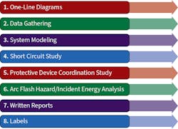
Figure 3 shows the incident energy analysis process. Each of the tasks listed is a crucial component of a complete analysis, and it’s very important that each is performed thoroughly and properly to create an accurate study.
Electrical one-line diagrams
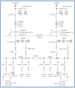
The process begins with the evaluation of the electrical one-line diagrams, which should be kept up to date per NFPA 70E. For the study to be accurate, it is helpful if existing electrical one-line diagrams show the full power distribution layout. The one-lines should identify the sources of power, voltage levels, and electrical equipment such as transformers, generators, switchgear, motor control centers, panelboards, and the protective devices (Fig. 4).
Data gathering and system modeling
Where electrical one-line diagrams are not available, the data gathering process must identify all this information. Once the data is gathered, a one-line diagram must be created based on it. To properly perform the analysis, the process should be very thorough, where all the information of the equipment is gathered, such as ratings of the equipment, arrangement of components on electrical one-line diagram, nameplate of every electrical device, ratings and trip settings of every protective device, and sizes and lengths of all conductors.
IEEE 1584-2018 now requires the electrode configuration and enclosure sizes to be considered in the calculations. It is critical to obtain the information on actual equipment so that the study is accurate. Shortcuts are often taken here, which can cause the study to be inaccurate or invalid. The electric utility contribution, or available fault current, is also an essential piece of the puzzle for proper analysis. It can be challenging to get this information from an electric utility. Many times, an infinite bus calculation is used when the actual fault current cannot be obtained. However, when an infinite bus is used, the clearing time would be much faster than it would be with the actual level of fault current (Fig. 5), which results in a false calculation.
• Isca = 28kA clears in 0.1 sec. (infinite bus fault current)
• Isca = 9kA clears in 1 sec. (actual fault current)
The gathered information is then typically put into engineering software in the form of a one-line diagram model with the correct information selected for each component. This provides the basis for comprehensive power system modeling in performing all types of analysis.
Short-circuit study
As part of the study, a short circuit analysis is performed to determine if the protective devices are properly rated to withstand a bolted type short circuit fault. To determine this, the maximum available fault current is calculated at each significant point in the system, and as an additional analysis, the bolted fault currents are converted into arcing currents. The results are determined based on the existing rating of the equipment.
Protective device coordination
Another important aspect is the protective device coordination study. This allows the engineer to properly coordinate the protective devices so that you don’t have an upstream breaker tripping before a downstream breaker in the event of a fault. If this happens, it could shut down critical equipment or possibly even an entire facility, depending on the configuration. In most cases, a protective device coordination study also allows the incident energy levels (or the arc flash hazard) to be reduced at various locations with recommended changes to existing settings on the breakers or relays.
Incident energy/arc-flash hazard analysis
The arc flash hazard (or incident energy) calculations are also performed as part of the study. As mentioned previously, the calculations are typically based on IEEE 1584; however, the calculations can be based on the equations depicted in NFPA 70E or NESC, depending on the type of facility and/or electrical equipment involved.
Written reports and labels
Of course, as part of the final deliverables, a written report is provided to inform the owner of the results and recommendations. Labels are also applied to the electrical equipment, which shows the incident energy, PPE requirement, arc flash boundary, and working distance for that piece of equipment.
Electrical one-line diagrams are typically provided with the deliverables as well, where the drawings can be customized to show specific incident energy levels, short-circuit current, etc., on the drawings.
Also, as mentioned before, since this is an engineering report and/or study, the documents are typically required to be certified by a licensed P.E.
Update Requirements
What do you do after the analysis is complete? Now you need a plan to keep it properly maintained and updated.
Per NFPA 70E Sec. 130.5, an incident energy analysis should be updated when major system modifications take place. This accounts for changes in the electrical system that could affect the analysis. In addition, the studies must be reviewed at a minimum of every five years. Changes to the available fault current or electric utility equipment could greatly affect the analysis.
Make sure you keep the studies up to date. If the information is not kept current, it is unreliable.
Summing It Up
Hopefully, you now understand the steps involved in an incident energy analysis and what regulations or standards govern the process. Proactively managing these activities helps protect your employees and equipment, and reduces your risks of potential fines and litigation.
Downey is the Principal Engineer for AVO Training Institute (www.avotraining.com). He is an active member of the IEEE 1584 Working Group – Guide for Performing Arc-Flash Hazard Calculations, IEEE 1814 Working Group – Recommended Practice for Electrical System Design Techniques to Improve Electrical Safety, and serves as an alternate on the NFPA 70E Technical Committee. He can be reached at [email protected].
About the Author
Ryan Downey, P.E.
Downey is a principal engineer for AVO Training Institute (www.avotraining.com). He is an active member of the IEEE 1584 Working Group – Guide for Performing Arc-Flash Hazard Calculations and IEEE 1814 Working Group – Recommended Practice for Electrical System Design Techniques to Improve Electrical Safety. He can be reached at [email protected].