Five Steps for Creating an Electrically Safe Work Condition
You most likely have been trained in the requirements of NFPA 70E, Standard for Electrical Safety in the Workplace. However, the amount of information you’re expected to retain can sometimes be overwhelming and confusing in a training session. Even though the knowledge is required, workers need a routine set of practical everyday steps they can apply in the field. When planning the job, following five electrical safety steps can help to ensure you accomplish the job safely. These steps (developed from the NFPA 70E-2021 standard) are used in the following scenario for this article.
The scenario
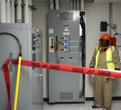
The switchboard in Photo 1 must be verified to be in an electrically safe work condition before a breaker can be replaced. The term “electrically safe work condition” more accurately describes the task to be accomplished rather than just “de-energized.” In this scenario, the switchboard is fed from a 480V insulated case circuit breaker located elsewhere in the plant. Opening this breaker does not guarantee all power is de-energized. Through the completion of five practical steps, the switchboard can be verified to have all sources of power removed, ensure it is safe to perform the work, and identify the personal protective equipment (PPE) and safe work practices necessary to protect the worker in the unlikely event something should go wrong.

STEP 1: Complete a risk assessment.
A risk assessment is the first step in creating an electrically safe work condition. It is a systematic process of identifying the electrical hazards that appear in each step of the job, determining the likelihood that such a hazard may occur, and understanding the severity that this hazard may pose to the safety or health of the worker. The risk assessment determines if the job can be done safely as-is or if additional protective measures are needed. Any risk must be reduced to an acceptable level before the job can be performed.
Every job, electrical or not, will always involve some risk. Simply driving to work involves risk. We choose to keep our vehicles in safe working order, follow the rules of the road, accept the remaining risk, and drive safely to work. Electrical work is no different. We ensure our equipment is safe, follow safe work practices, and safely perform the job.
Two electrical hazards must be examined and the results documented before the start of each job: the shock hazard and the arc flash hazard. Using standardized forms and developing standard checklist-type procedures for routine tasks, such as electrical lockout/tagout, can greatly reduce the amount of time needed to complete the risk assessment.
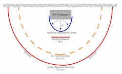
Interpreting the arc flash warning label on the equipment is a logical place to start with the risk assessment. See Fig. 1 for the label and the Fig. 2 for a graphical representation. The potential severity of the hazards is easily identified, and boundaries/working distances are provided.
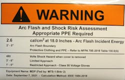
Arc flash warning labels are required on equipment likely to require servicing or maintenance after the installation as specified in Sec. 110.16 of NFPA 70, National Electrical Code (NEC). The information required to appear on the label appears in the NFPA 70E standard. The labeling requirement does not apply to dwelling units.
Arc flash warning labels are divided into two specific areas of content: shock information and arc flash information. The shock information provides the nominal system voltage. Working with 50V and above requires protective measures to be taken by workers. Note that the label indicates the hazard exists when the “cover is removed.” Of course, the 480V exist any time the switchboard is energized. However, with the switchboard covers in place, the worker is not exposed to this hazard. It is important to understand that closed doors and barriers (such as clear polycarbonate shields) may be used to prevent workers from exposure to electric shock through inadvertent contact with the live terminal or parts. Thus, the likelihood of electric shock is greatly reduced.
Other shock-related information on the label includes the limited approach boundary, the restricted approach boundary, and the minimum class rubber insulating gloves to be used.
The limited approach boundary (3 ft, 6 in. for a 480V hazard) identifies the distance from the exposed conductors at which a shock hazard exists. Only qualified persons may enter beyond this point. An exception does allow unqualified persons in this area if continuously escorted by a qualified worker. An example of this exception might be an apprentice learning to verify an electrically safe work condition.
The restricted approach boundary is an approach limit identifying an increased likelihood of electric shock. Only qualified persons are allowed to extend past this 1-foot limit and make contact with the exposed parts. “Making contact” is not touching an energized part with gloved hands! Making contact includes touching insulated test leads to “live” terminals, and, in rare occurrences, using an insulated tool to touch a terminal. Any items entering this area must be insulated (gloved hands, insulated test leads, and insulated tools).
The arc flash portion of the label identifies the severity of the arc flash at the working distance, which is the distance the head and chest must be kept from the exposed parts when working. Unprotected skin exposure to 1.2 cal/cm2 of incident energy for 1 second is likely to cause the onset of a second-degree burn. In the example, on this label there will be 2.6 cal/cm2 at the working distance of 18 in. The arc flash boundary on the label (2 ft - 5 in.) is the distance from the exposed parts at which the incident energy level drops to the 1.2 cal/cm2 – the possible onset of a second-degree burn.
A documented risk assessment outlines each step of the procedure can be safely performed, determining that in the unlikely event something should go wrong the worker will be protected (assuming appropriate PPE is being worn and safe work practices are being followed). If the analysis of any step in the procedure reveals too great a likelihood of an incident occurring — or there is a danger to the safety of the worker — the work cannot be performed until steps are taken to reduce the risk to a safe level. The results of the risk analysis are then incorporated into the electrical job safety plan, which is all discussed in the job briefing.
STEP 2: Select and inspect PPE.
The risk assessment is reviewed, and the electrical PPE identified in the written assessment is selected and inspected for the job (Photo 2). The risk assessment reveals 2.6 cal/cm2 at a working distance of 18 in. Workers must not allow their head or chest to get any closer than 18 in. As the distance to exposed parts decreases, the incident energy values increase exponentially, and workers may not be properly protected from an arc flash if they are closer than this working distance. Arc-rated clothing must be selected to protect all parts of the body and rated at or above the 2.6 cal/cm2 on the label. NFPA 70E Table 130.5(G) provides the complete list of electrical PPE to be worn.

The label reveals a “480V shock hazard when cover is removed.” Adequate shock protection includes rubber insulating gloves, test equipment leads, and tools rated at or above the 480V. Any tools or parts of the body taken inside of the restricted approach boundary must be insulated to at least this level.
All PPE must be inspected before use. A calorie value labeled on the outside of the garment is not sufficient information. Workers must look for a label that states the “arc thermal performance value (ATPV)” or “energy breakopen threshold (EBT)” on the label. Those values determine the garment’s actual rating. Typically, the ATPV value is expressed on the label. Should both the ATPV value and the EBT be present on the label, use the lesser of the two values to determine the garment rating. Both ratings are expressed in cal/cm2. Arc-rated clothing must be free from physical damage, holes, or contamination. Fasteners and closures must work properly. Once donned, sleeves must be rolled down, fasteners properly closed, and there must be room for adequate visibility and movement.
Insulated rubber gloves and leather protectors must also be inspected daily before use. This includes a visual inspection for any damage or contamination and an air test for the rubber glove. If a glove leaks air, it will leak electricity. A proper air test helps to ensure the integrity of the rubber insulation.
Meters and test equipment must be inspected for any signs of physical damage, including the test leads. Voltage ratings must be verified to fall above the rating of the nominal system voltage. Meter and test lead CAT ratings must be adequate for the measurement location in the distribution system. CAT-rated meters are designed to minimize or reduce the possibility of an arc flash occurring inside the meter during a voltage surge. The ratings are usually located near the input jacks. For the switchboard in this scenario, a minimum of at least CAT III 600V is required.
STEP 3: Verify equipment is suitable for normal operation.
To reduce the likelihood of occurrence of either a shock or arc flash incident, electrical equipment must be examined to ensure it is suitable for normal operation. Even though the upstream power source has been locked and tagged, the switchboard must be assumed to be energized until verified electrically safe. NFPA 70E identifies six items that must be examined before work begins.
- Proper installation of equipment. It is not intended for the electrical worker to become an electrical inspector. However, even NFPA 70E points out that workers should know the NEC to carry out this step. Improperly supported conduit runs, equipment, and lack of clear working space as defined in NEC Sec. 110.26 are examples of items that should be readily identified by the experienced eye. Additionally, referring to facility drawings and one-line diagrams can help to provide insight. The worker should know the original installation was inspected by an authority having jurisdiction and any subsequent changes have been properly documented and inspected. In the end, it is the qualified worker performing the job who must make the determination that the equipment has been installed properly.
- Equipment is properly maintained. This step is best determined through the examination of maintenance records. NFPA 70B, Recommended Practice on Electrical Equipment Maintenance, provides an example of a maintenance labeling system that can offer ready information to workers.
- Equipment must be used per its listing/labeling and manufacturer’s instruction. Generally, this is not an issue; however, modifying equipment in the field often results in concerns in this area. Carefully inspect modifications.
- The equipment doors must be closed and secured.
- All equipment covers must be in place and secured. Missing bolts used to secure covers is a common issue; replace as necessary. Additionally, if possible, completely walk around the equipment for proper inspection.
- There must be no signs of impending failure. Electrical work experience is the key to making this determination. The smell of burnt insulation, excessive rust, water dripping on or around equipment, and discoloration on panels are examples of what the trained eye observes.
STEP 4: Set up barricades.
Physical barricades prevent access to certain areas by unauthorized persons. Depending on needs, several types of barricade materials are available on the market – from tapes or cones to A-frame wood or metal structures to folding gates. NFPA 70E also requires safety signage to be used in conjunction with the barricade.
To determine the placement of the barricade, examine the job plan, and use the distance of either the limited approach boundary or the arc flash boundary — whichever is greater. It is also important to observe the layout of the room. For example, is it possible for someone to enter through another door and unknowingly be inside of an approach boundary?
In some cases, it may be necessary to station an additional person to warn other personnel to stay clear of an area. Such persons must not have any other job duties.
In this scenario, the arc flash label states the arc flash boundary is 2 ft, 5 in. The limited approach boundary stated is 3 ft, 6 in. Since the limited approach boundary is the greater distance, the barricade must be placed at least 3 ft, 6 in. back from any live parts that may be exposed when the switchboard cover is removed.
STEP 5: Establish an electrically safe work condition.
Lockout/tagout is the term often used in the field to describe creating an electrically safe work condition. However, locking out the feeder breaker to the switchboard may not make that equipment safe to work on electrically. Standby generators can start automatically, their output breakers close, and an automatic transfer switch (ATS) can operate to re-energize the switchboard. Some equipment may have space heaters powered from a nearby panelboard; backflow through a pump will cause an induction motor to operate as a generator and has been known to severely injure a worker. The electrically safe work condition looks at all possible sources of supply to equipment and verifies that each is absent.
Should it be necessary to work on electrical equipment other than for diagnostic testing (voltage measurements while troubleshooting), an energized electrical work permit must be completed. This document requires a qualified person to describe the work to be done and an explanation of why an electrically safe work condition cannot be established. These work permits require management approval to perform the work.
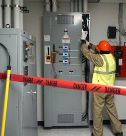
The following eight steps are used to create and verify an electrically safe work condition for the switchboard (Photo 3):
- All possible sources of electrical supply to the switchboard were determined using electrical drawings and identifying equipment using the equipment labels.
- The loads fed by the switchboard were first shut down, and the insulated case feeder breaker supplying the switchboard was opened.
- Mechanical indication on the feeder breaker was used to verify the breaker is “open.” When possible, visually verify all blades are open on disconnect switches. Drawout-type circuit breakers are withdrawn to the test or fully disconnected position.
- The system was examined to ensure capacitors were not present in the switchboard circuit supply or loads. Capacitors store electrical energy and must be properly discharged.
- Devices that store nonelectrical energy were not found in the system. ATSs or other devices that could re-energize the switchboard were not in the electrical system.
- The lockout/tagout device was applied to the feeder breaker per the facility’s procedure.
- Once the cover to the buswork was removed, a multimeter was used to verify the absence of voltage in the switchboard. Both phase-to-phase and phase-to-ground measurements were taken and read 0V. However, that does not guarantee the meter was working properly. A three-point test method or “Live-Dead-Live” test is used to verify the absence of voltage. The meter was first verified to be working properly on AC voltage by testing it with the meter proving unit hanging adjacent to the meter. Refer back to Fig. 2. After the 0V reading was obtained (phase-to-phase and phase-to-ground), the multimeter was once again verified to be operating properly using the meter proving unit.
- The final step would be to install temporary personal protective grounds if needed. However, it was determined there was no possibility of induced voltages, stored electrical energy, or other potential dangers. Temporary grounds were not required.
Completion of these eight steps has placed the switchboard into an electrically safe condition. Since the equipment is now verified to be in an electrically safe work condition, electrical PPE (insulated rubber gloves, face shield, arc-rated clothing, etc.) can be removed, and work on the equipment can begin.
In summary
Placing equipment in an electrically safe work condition is always the preferred method of work. First, conduct a risk assessment, examining each step of the job to ensure any risk is reduced to an acceptable level. Use the risk assessment to complete a job safety plan and conduct a job briefing. Select, inspect, and don the appropriate PPE to protect all parts of the body. Make sure the equipment is suitable for normal operation before work begins. Set up a barricade at the appropriate distance from the equipment. Ensure all steps necessary to verify an electrically safe work condition are completed — especially the Live-Dead-Live test. If any questions or doubts arise — or if the job scope changes for any reason — immediately stop work. Then reassess the job as necessary, revise the job safety plan, conduct a new job briefing, and resume work. Applying these five practical electrical safety steps to job safety planning will not only reduce shock and burn injuries but will also help ensure you go home safely each day.
Randy Barnett is a certified electrical safety compliance professional (CESCP). He can be reached at [email protected].