A Safer Approach to Verifying the Absence of Voltage

Ensuring the safety of employees in the workplace is undeniably the foremost responsibility of any company. While the importance of workplace safety is universally acknowledged, a disconcerting question arises: Why do incident rates of electrical injuries — and, in some tragic cases, fatalities — persist without showing a significant decline year over year despite the purported priority placed on employee safety?
Workplace electrical injuries and fatalities
Most electrical accidents occur because people are working on or near equipment that is:
- Thought to be dead but is live.
- Known to be live, but those involved do not have adequate training/appropriate equipment or have not taken adequate precautions.

A recent report by the Electrical Safety Foundation International (ESFI) covering workplace accidents from 2011 to 2022 raises concerns. The data, depicted in Fig. 1, shows that approximately 48% of reported fatalities occurred while working with or near live electrical parts, highlighting the increased vulnerability associated with working near live conductors.

Despite advancements in safety protocols, ESFI’s findings in Fig. 2 and Fig. 3 reveal there hasn’t been a significant decrease in fatalities and injuries related to electrical incidents over the years. Additionally, it’s noteworthy that these accidents aren’t limited to inexperienced workers. Data in Fig. 4 from the Survey of Occupational Injury and Illness (SOII) on nonfatal work injuries caused by exposure to electricity by workers years of service indicates that most nonfatal electrical injuries involve workers with over a year of experience with their employer.


These findings emphasize that even experienced personnel are susceptible to accidents, suggesting that human error remains a significant factor contributing to such incidents.
Use of various instruments for verifying the absence of voltage
Both NFPA 70E, Standard for Electrical Safety in the Workplace, and CSA Z462, Workplace Electrical Safety, have undergone significant changes over the past few years, allowing for the acceptance of various instruments for verifying the absence of voltage.
Multimeters
The 2015 edition of NFPA 70E stressed the importance of a safer work environment by recommending the use of an adequately rated test instrument, which is often interpreted as a multimeter, to directly test phase conductors or circuit paths. This method involves opening electrical cabinets, wearing proper safety gear, and making direct contact with equipment. This approach of direct testing poses challenges due to potential human errors, including the risk of unintentional contact with live conductors or the incorrect selection of inadequately rated test equipment.
Data from Fig. 2 and Fig. 3 illustrate that from 2015 to 2017 there was no significant reduction in fatal and nonfatal injuries. Recognizing these challenges opened up opportunities for exploring alternative methods and technologies to enhance electrical safety in the workplace.
Voltage test ports
In 2018, the NFPA 70E standard saw an update in Sec. 120.5, introducing an exception (Exception No. 1 to Rule 7). This exception allowed the use of a properly rated permanently mounted electrical test device to verify the absence of voltage. This led to the widespread adoption of voltage indicators and test ports for this crucial test. The rationale behind this approach was simple: Conducting the test with the door closed reduced the risk of unintentional contact with current-carrying conductors. The expectation was that the industry would see a significant decrease in fatal and non-fatal incidents.
However, despite the increased use of voltage indicators and test ports, there hasn’t been a significant decrease in incident rates. Figure 2 and Fig. 3 show there’s been no major decline in fatalities and/or injuries from 2018 onwards. This raises the question of why this is the case. Here are two potential answers.
- Seeing 0V at the end of a test port doesn’t ensure that there’s no voltage on the current-carrying conductors. There are situations (such as when wires are missing or loose or if a fuse between the test port and the current-carrying conductors is blown) where the meter may show 0V even if there’s still voltage.
- Voltage test port results may not be fully trusted by qualified workers, potentially prompting them to open the door of the electrical cabinet for a physical inspection. This action exposes workers to the risk of unintentional contact with live conductors, thereby defeating the purpose of conducting the test with the door closed.
It’s worth mentioning that in the 2024 edition of NFPA 70E, ANNEX O.2.4 includes the use of voltage test ports as an additional Safety-by-Design method. These voltage test ports are recognized as effective design features for minimizing risks related to arc flash or electric shock hazards. By enabling voltage measurement and troubleshooting without the need to physically open the door, they significantly reduce exposure to potential hazards.
Absence of voltage tester
An absence of voltage tester (AVT) is designed to confirm the absence of electrical voltage without the need to physically open equipment doors, thus minimizing the risk of exposure to electrical hazards. Its significance has been acknowledged by NFPA 70E 2021, which updated Rule 7 of Section 120.5, replacing the term “permanently mounted test device” with “permanently mounted absence of voltage tester” for clearer safety guidelines. Additionally, it mandated that AVTs adhere to the standards set by UL 1436.
The evolution continues with the NFPA 70E 2024 update in Rule 7 of Section 120.6, emphasizing the necessity of testing “at each point of work.” This highlights the crucial aspect of conducting voltage tests directly where tasks are being carried out, further enhancing workplace safety standards.
Understanding how an AVT works
An individual simply presses a button to initiate a test sequence that fulfills all the requirements for verifying the absence of voltage. The AVT ensures its satisfactory function via a supervisory circuit that conducts continuity checks to confirm secure and correct connections. Only after these steps are satisfied will the AVT check for the absence of both AC and DC voltage, including phase-to-ground and phase-to-phase. If everything passes, the system repeats the steps a second time. If the second test is successful — and there is less than 3V AC or DC in the circuit — a green light(s) indicator shows the situation is safe, and the electrical panel door can be opened.
In the case of an unsuccessful test, amber light(s) stay illuminated, indicating a potentially unsafe condition. The next step is to retest the installation and wait for an additional 10 sec. If the test is unsuccessful a second time, the only option is to put on personal protective equipment (PPE), open the door, and troubleshoot the situation. This push-to-test feature of AVTs enhances efficiency in a facility, eliminating the need for manual testing and minimizing exposure to electrical dangers.
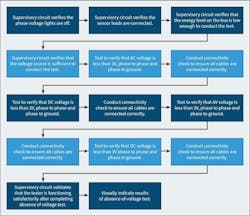
The AVT’s entire test sequence is visually represented in Fig. 5.
To guarantee safety and effectiveness, Section 12 of UL 1436 outlines the operational standards for AVTs. These guidelines include specific testing procedures and requirements, mandating compliance with Functional Safety IEC 61508 and SIL 3 certification. SIL 3 certification underscores the fail-safe nature of the product, signifying that the occurrence of a hazardous condition must happen less than once in 10,000,000 hours of operation, on average. This rigorous criterion implies a potential failure rate of less than one instance in more than 1,000 years.
AVT benefits
AVTs reduce the likelihood of human error in verifying the absence of voltage. Unlike traditional methods that may involve physical contact with live parts, AVTs offer a non-contact solution, minimizing the risk of accidents.
The display unit of an AVT is mounted on the door and connected to the control module through a communication cable, ensuring that no hazardous voltage reaches the door. The tester is installed on the load side of a disconnect switch, with no connections to the line side. When operational, the device has no more than 3V.
AVTs should instill confidence in workers by providing a reliable and standardized method for verifying de-energization. This confidence should contribute to a positive safety culture within the workplace.
Conclusion
AVTs play a pivotal role in enhancing electrical safety by providing a reliable and standardized method for verifying the absence of voltage. Its accuracy, user-friendliness, and integration with safety procedures make the device a valuable tool for reducing electrical hazards and fostering a safe work environment.
UL 1436 Guidelines
As per UL 1436, Standard for Outlet Testers and Similar Indicating Devices, an absence of voltage tester (AVT) is defined as a permanently mounted test device that is used to verify that a circuit is de-energized before opening an electrical enclosure that contains energized electrical conductors or circuit paths.
[1] An AVT shall be provided with the means for the user to initiate the test for the absence of voltage.
[2] An AVT shall provide the user with a visual indicator to confirm the absence of voltage after the absence of voltage test has been performed. The visual indication shall be green.
[3] The AVT supervisory circuit has incorporated a secondary power source and shall have no internal failure that would affect performance.
[4] The AVT shall incorporate a supervisory test circuit to verify that the tester is functioning properly before and after the AVT performs voltage measurements.
[5] The AVT visual indicator shall only illuminate green when all phase-to-phase and phase-to-ground voltages measure less than 3VAC or 3VDC.
[6] The AVT visual indicators shall not illuminate green unless the phase and ground leads are in direct contact with the circuit conductors being tested.
[7] The AVT visual indicator shall not illuminate green if a phase lead is connected to ground or the ground lead is connected to a phase conductor.
[8] The visual indicator shall not illuminate green unless the secondary power source is operational.
[9] The AVT shall comply with the Standard for Functional Safety IEC 61508 and achieve an SIL 3 rating.
About the Author
Sudhir Pandey
Sudhir Pandey is an electrical engineer for I-Gard Corporation in Mississauga, Ontario. He can be reached at [email protected].