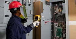
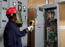
All objects emit infrared (IR) energy, known as a heat signature. IR tools detect and measure that energy. Using IR technology for troubleshooting and maintenance provides tremendous advantages across many industrial, commercial, and residential applications. One of the biggest advantages of IR tools for electricians is that — because the devices are noncontact — you can inspect equipment while it’s running while keeping a safe distance.
This expedites troubleshooting and reduces downtime. It also makes it practical to run more frequent maintenance checks and thereby increase the likelihood of detecting electrical problems at an early stage. You still must comply with all electrical measurement safety standards and wear proper personal protective equipment (PPE), but you save time by not having to perform lockout-tagout procedures before starting the inspection.
Infrared technology is available in a range of tools, including infrared cameras (also called thermal imagers), visual IR thermometers, and IR thermometers (often called heat guns). Abnormal heat (or lack of it) is a common indicator of many problems in electrical supply or distribution systems, and IR technology is dedicated to detecting temperature differences. Thus, these tools are especially useful for electrical troubleshooting to find issues such as:
• Overloaded systems or excessive current
• Loose, tight, dirty, or corroded connections
• Component failures
• Wiring mistakes or under-specified components
• Power quality issues like phase unbalance or harmonics
IR Tool Options
There are three basic categories of IR measuring tools, each suited to a different level of inspection:
IR thermometers — IR thermometers measure temperature in a single spot. If you already know where the problem is, you can point the IR thermometer at it and get a digital readout of the average temperature of the area. These are good for quickly surveying transformers, electrical panels, breakers, motors, and conductors for hot spots.
Visual IR thermometers — Visual IR thermometers bridge the gap between IR thermometers and IR cameras (also called thermal imagers). Like IR thermometers, visual IR thermometers are point and shoot, but they also provide a low-resolution thermal image and include a digital camera so you can blend a visible light image with the heat map overlay to pinpoint the location of a problem. You can quickly locate abnormal temperatures on electrical panels and wiring, breakers, panels, switch gear, and fuses.
IR cameras — IR cameras (thermal imagers) provide higher resolution images and much more information about the target objects than a visual IR thermometer. They also are effective from longer distances, which allows electricians to inspect equipment from outside the arc flash zone. Common applications include inspecting switchgear cabinets, electrical panels, three-phase conductors, and overhead cable trays.
IR windows further enhance the safety benefits of IR technology by allowing you to perform IR scans and visible light inspections of energized electrical equipment through a specialized heavy-duty window, rather than having to open the door to the panel or switchgear enclosure. This significantly reduces the potential for arc flash incidents.
Applying IR Tools to Everyday Electrical Applications
Electricians can use IR tools both to diagnose problems and to verify that repairs are successful. Getting the best results with an IR device requires training on the proper use of the tool and how different materials surfaces emit, absorb, or reflect IR energy.
Shiny metal or polished surfaces, for instance, can show incorrect readings on your IR device if you don’t account for what is called the “emissivity” of material surfaces. Knowing the emissivity and adjusting for it when needed will allow you to better use your IR tool to take accurate temperatures and understand the information it is providing.
With this knowledge and training you are ready to tackle some of the most common electrical problems that can be found with IR tools:
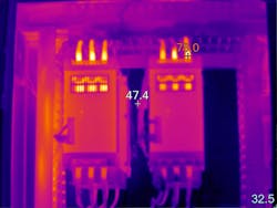
3-phase imbalance — Start by capturing thermal images of electrical panels and other high-load connection points such as drives, disconnects, and controls. Wherever you discover higher temperatures, follow that circuit with your thermal imager and examine associated branches and loads.
Compare all three phases side-by-side and check for temperature differences. A cooler-than-normal circuit or leg might signal a failed component. More heavily loaded phases will appear warmer. A hot conductor may indicate that it is undersized for the normal load or is overloaded.
However, an unbalanced load, an overload, a bad connection, and harmonics can all create a similar pattern, so follow up with electrical or power quality measurements to diagnose the problem.
Be aware that voltage drops across the fuses and switches can also show up as unbalance at the motor, and excess heat at the root trouble spot. So, before you assume the cause has been found, double-check with a thermal imager and use a multimeter or clamp meter to take current measurements.
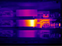
Connections and wiring — Scan for connections that have higher temperatures than similar connections under similar loads. Higher temperatures could indicate a loose, over tightened, or corroded connection with increased resistance. Connection-related hot spots usually, but not always, appear warmest at the spot of resistance, and cool at further distances from that spot.
In some cases, a cold component is abnormal due to the current being shunted away from the high-resistance connection. You may also find broken or undersized wires or defective insulation. NETA (InterNational Electrical Testing Association) guidelines state that when a temperature difference between similar components under similar loads exceeds 15°C immediate repairs should be performed.
Fuses — If a fuse shows up hot on a thermal scan, it may be at or near its current capacity. However, not all problems show up as heat. For example, if a fuse is blown, it will produce a cooler than normal temperature.
When evaluating an electrical hot spot, notice whether the heat continues back along the wire toward the load — indicating a load related problem — or is isolated to the connection, indicating a connection-related problem.
Motor control centers (MCC) — To evaluate an MCC under load, follow safety procedures to open each compartment and compare the relative temperatures of key components, including bus bars, controllers, starters, contactors, relays, fuses, breakers, disconnects, feeders, and transformers. Follow the previous suggestions for inspecting connections and fuses and identifying phase imbalance.
Transformers — For oil-filled transformers, you can use a thermal imager to look at high- and low-voltage external bushing connections, cooling tubes, and cooling fans and pumps, as well as the surfaces of critical transformers. The cooling tubes should appear warm. If one or more tubes is comparatively cool, oil flow is probably restricted. Keep in mind that like an electric motor, a transformer has a minimum operating temperature that represents the maximum allowable rise in temperature above ambient (typically 40°C). A 10°C rise above the nameplate operating temperature can reduce the transformer’s life by up to 50%.
It is much more difficult to detect problems in dry transformers, with an infrared imager because their coil temperatures are so much higher than ambient temperatures.
Play it Safe
There’s little question that IR technology can help reduce electrical danger for both troubleshooting and maintenance tasks. As IR tools and IR windows become more affordable and easier to use, they are rapidly becoming a go-to tool in electrical worker toolbelts and a critical component to company safety programs.
Sandhu is a thermography services manager for Fluke. He has worked in electronics design and thermal imaging for more than 35 years. He can be reached at [email protected].
Sidebar: Pro Tip
Measure the load at the time of each scan so you can properly evaluate your measurements against normal operating conditions. To get the best results from an infrared (IR) inspection, the target equipment should be warmed up and operating at the rated voltage and at steady state conditions — with at least 40% of the typical load.
About the Author
Sat Sandhu
Thermography Services Manager
Sandhu is a thermography services manager for Fluke. He has worked in electronics design and thermal imaging for more than 35 years.


