With growing concerns about climate change, pollution, energy supply, aging infrastructure, and the desire for clean energy, the notion of homegrown, environmentally responsible energy is looking better every day. Solar technologies (specifically photovoltaic systems) have the potential to revolutionize how we generate power for a wide range of applications. The Earth receives enough solar energy from the sun in one hour to satisfy the world’s energy demand for an entire year. So the fact that the globe is not relying on this technology more is a travesty.
Photovoltaic cells and modules
Photovoltaics (PV) is a technology that uses the electrical properties of various types of semiconductor materials to directly convert sunlight into electric power. The resulting electricity is direct current (non-sinusoidal). The basic physical process is known as the PV effect. When high-energy photons of sunlight strike a semiconductor material and are absorbed, the energy is transferred to the electrons in the semiconductor material. The extra energy excites the electrons to the point where they break free from their associated atom. The free electrons are directed through an external circuit to a load where the flow of electrons (i.e., current) can do useful work. This process occurs continuously as the semiconductor material is exposed to daylight.
PV cells are the basic building block of a PV module and are typically made of crystalline silicon material. Many other materials are available for PV cell production, but crystalline silicon dominates the power generation market.
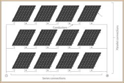
Monocrystalline silicon cells are made from a single silicon crystal, resulting in high efficiency (16% to 21%). Polycrystalline silicon is composed of many silicon crystals and has a lower efficiency (12% to 15%). The individual PV cells are combined in series and parallel connections to form modules, often referred to as panels. Series connections are made to build voltage. Parallel connections are made to build current. The power output of the module is voltage multiplied by the current (P = V × I). Standard modules are either 60 or 72 cells and rated typically 270W to 300W. Modules with more cells or higher wattages are available. Similar to PV cells, modules are connected in series and parallel to increase voltage and current. A group of modules is called an array (Fig. 1).
Photovoltaic systems
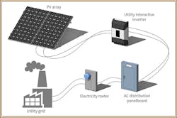
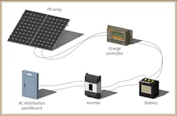
A PV system is defined as all the components required to allow the system to produce useful power. This includes modules, wiring, conduit, combiner boxes, overcurrent protective devices (e.g., fuses and circuit breakers), disconnect switches, inverter(s), meters, mounting hardware, etc. PV systems can be configured in various ways, such as grid-tied (utility interactive), as shown in Fig. 2, or off-grid (stand-alone), as shown in Fig. 3.
Grid-tied is the most common PV system configuration because it’s the easiest to design and less expensive compared to a stand-alone system, which relies on batteries. The application of the system will determine the system configuration. With respect to size classification, residential systems are rated less than 20kW, commercial systems are 20kW to 1MW, and utility systems are more than 1MW. Again, these are general guidelines.
Site survey and planning
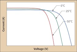
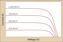
The first stages of a PV project involve researching the location and surveying the site. It is crucial to know the climatic conditions — most notably the high and low temperatures and solar insolation. The Solar America Board of Codes and Standards has a reliable reference map for obtaining temperature data. Temperature is perhaps the most important factor when sizing the array and balance of system (BOS) components. This is due to the fact that the voltage and current produced by the cells is dependent on the ambient temperature and insolation at the site. That is, the voltage of the module is higher in colder temperatures, and the current increases with higher insolation values (Fig. 4 and Fig. 5).
It’s also important to consider factors such as wind speed, corrosion, severe weather, lightning strikes, seismic activity, and the potential for vandalism and theft. Local building codes and city ordinances, permitting, inspection, interconnection requirements, and financial incentives must also be investigated prior to design. These factors may influence how the system is designed and installed.
The location should be surveyed prior to design to evaluate shading concerns and existing roof conditions. Shading is a huge concern. Even a small amount of shade during the day could have a detrimental effect on system performance. The age/condition of the roof may warrant a total roof replacement as the life of the PV system is 30 years or more.
Following the initial site survey, array sizing is the next task to consider. At this point, the first question to ask is, “what am I designing for?” The answer will influence how the system is designed. For example, are you trying to maximize annual energy yield? Maximize the kW rating? Are you working within a limited footprint? Are you working with a fixed budget? You won’t be able to design an array layout until you’re aware of the objectives and constraints.
Most PV modules are manufactured to a standard dimension (about 66 in. × 38 in.). By using architectural design software or computerized drafting, you can quickly create different layouts using portrait or landscape module orientation, different tilt angles, etc. This is a trial-and-error exercise where the goal is to determine the most efficient layout while satisfying your constraints and objectives. There will be several iterations before you arrive at a preferred layout. You must also calculate the row spacing distance to avoid inter-row shading. You can use trigonometry to hand calculate the spacing, or use an online calculator. The approximate rule of thumb for spacing between rows should be 2.5 to three times the height of the tilted module.
Your final PV array layout provides the total quantity of modules, which will give the DC power rating for the system. The rule of thumb for array size based on area is 8 to 12 W/ft2. A useful tool for estimating annual energy production is the PVWatts calculator available from NREL. It allows you to quickly estimate your production based on location, tilt angle, and other factors. More sophisticated designers may choose to use a more robust program for PV system modeling.
Photovoltaic system calculations
The basic grid-tied system consists of a PV array, the AC panelboard, and branch load circuits. These components are interconnected and tied back into the grid via the electric utility meter. Calculations are required to properly connect the modules, select the inverter, and size the circuits. The first step is connecting the modules to build an array. Modules connected in series are referred to as series strings. The National Electrical Code (NEC) refers to a series string as a PV source circuit.
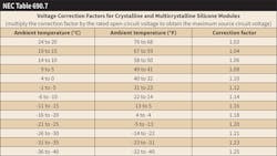
The quantity of modules that can be connected in a series string is limited by the system operating voltage, typically 600V. Large commercial or utility systems could be higher at 1,000V. According to Sec. 690.7 of the NEC, the maximum PV source circuit voltage shall be calculated as the sum of the rated open-circuit voltage of the series connected modules corrected for the lowest expected ambient temperature. The open-circuit voltage (VOC) is the maximum voltage generated by a PV module and can be obtained from the PV module data sheet. If a data sheet is not available — or there are multiple modules being considered — then the NEC provides a generic table of correction factors for crystalline silicon modules (Table 1).
Example 1: Given the NEC information in Table 1 and the PV module data in Table 2, calculate the maximum quantity of modules you can connect in series. Assume the system voltage is 600V, and the location is Detroit, Mich.
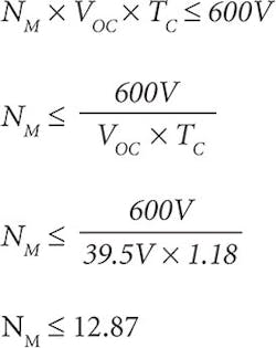
The first step is to go to Solar ABCs and find the lowest ambient temperature in order to determine the proper correction factor. The extreme minimum is -19°C. Based on NEC Table 690.7, the correction factor would be 1.18. The maximum number of modules (NM) connected in series is given below.
The maximum quantity of modules connected in series without exceeding the 600V based on the location is 12 modules. If string sizing doesn’t seem like fun to you, then there are online string sizing programs to help.
Once you have the string size, then you can move on to the combiner box. A combiner is a box that “combines” multiple series strings — that is, there are multiple inputs and a single output. Think of it as the opposite of a panelboard. The system may or may not need a combiner box depending on the quantity of strings and the capabilities of the inverter.
The PV source circuit maximum current is given as the module short circuit current (ISC). This is the current generated by the module when exposed to sunlight with the output terminals shorted. The short-circuit current is used when parallel connecting the series strings. The PV output-circuit current is the sum of the PV source circuit currents.
NEC Sec. 690.8 has specific requirements regarding the calculation of the maximum circuit currents, ampacity, and overcurrent device ratings. This Code Section requires you to multiply the PV source circuit current by 125% to account for the fact that PV modules can produce higher currents under high irradiance conditions (i.e., current increases with more sunlight). Therefore, the PV output circuit current is the sum of the source circuit currents, including the 125% factor.
Another 125% factor must be applied when calculating wire ampacity and overcurrent protective device ratings to account for continuous equipment operation (more than 3 hours). Please note the string sizing program already mentioned can also perform the task of inverter selection based on your array power rating and string size.
Example 2: Given a PV module with the values in Table 2, calculate the PV source circuit and output circuit currents used to size wire ampacity and overcurrent protective device ratings. Assume your plan layout produced a PV array with 96 modules.
96 modules provides 8 strings (assuming 12 modules per string). The maximum PV source circuit current (ISCC) would be equal to the module short circuit current (9.71A) multiplied by 125%. The ampacity used to size PV source circuit conductors would require an additional 125% multiplier.
ISCC = ISC × 1.25 × 1.25
ISCC = 9.71A × 1.25 × 1.25
ISCC = 15.17A
The ampacity used to size the PV output circuits (IOCC) would be the sum of the ISCC values calculated above.
ISCC = ISCC × NS
ISCC = 15.17A × 12
ISCC = 182.04A
The PV output circuit ampacity, combiner box ampacity and inverter current rating would need to be rated for at least 182A.
The next step is inverter selection. The basic function of the inverter is to change the DC output of the PV array to alternating current (AC) for use in the building. Modern-day inverters use power electronics to accomplish this. Inverters fall into the following three categories: micro, string, and central.
Micro inverters are small module-level inverters that convert the DC output to AC at each module. When mounted directly to the module, they are referred to as AC modules. The advantage of the micro inverter is that they allow greater tolerance for shading, and modules can be mounted at different tilt angles and facing different directions. This helps when you have a roof with different slopes and orientations. String inverters are suited for small-size to medium-size PV arrays and combine a small quantity of series strings together at the inverter without the need for a combiner box. Central inverters are the largest inverters and are rated for higher kW values. They are made for large commercial and utility-scale projects.
The inverter size should be chosen to be lower than the DC rating of the PV array — about 80% to 100% of the array DC power rating. This “derate” factor accounts for typical systems losses. Sizing the inverter equal to or greater than the array DC power rating simply wastes money. Be sure the inverter input current and voltage range is compatible with the voltage and current of the PV array.
At this point, the output of the inverter typically connects back into the building AC system. The most common method is a back-fed circuit breaker within a building panelboard (Fig. 6). NEC Sec. 705.12 says the sum of the OCPD ratings of the circuits supplying power to a panelboard bus bar shall not exceed 120% of the rating of the bus bar. The PV circuit breaker also needs to be suitable for back-fed operation.
Additional Code requirements
Other notable Code requirements are specified in Secs. 690.5, 690.11, and 690.12. Section 690.5 states PV arrays shall be provided with ground-fault protection capable of detecting and interrupting a ground fault in the DC current-carrying conductors and components. Section 690.11 requires PV systems to be protected by a DC arc-fault circuit interrupter. Both of these Sections of the Code are intended to prevent or mitigate fires associated with ground faults and arcing-type faults occurring in DC circuits.
Section 690.12 requires rapid shutdown of PV systems on buildings. The intent of this requirement is to control (shut off) the DC conductors that near the array and remove power from them quickly during an emergency. This is important for firefighters and first responders to ensure power is off when trying to extinguish a fire. Please note that there is no way to turn off PV modules. PV modules will stop producing current only when the sunlight is no longer striking the modules.
Nowicki, P.E., is the electrical engineering discipline leader at SmithGroupJJR’s Detroit office. He holds a bachelor’s degree in electrical engineering and a master’s degree in alternative energy technology. He can be reached at [email protected].
SIDEBAR: The Sun’s Power
Solar irradiance is defined as the power of solar radiation per unit of area, measured in watts per square meter (W/m2). Earth’s solar irradiance constant is approximately 1,366 W/m2 (nominally 1,000 W/m2). Solar irradiation or solar energy is the solar power accumulated over time. The unit of measure is watt-hours per square meter (Wh/m2). The greater the solar irradiance for a given location, the more energy is generated. The preceding information is necessary for interpreting insolation maps (insolation is another term for solar irradiation). Insolation maps are used to rate the solar energy resources of a location. The National Renewable Energy Laboratory (NREL) produces insolation maps for reference.
It’s important to also understand the sun path or solar window for a given location, which depends on geographical location and time of year. The two angles most important to PV system designers are the azimuth angle (relationship to due south) and altitude angle (the sun elevation angle) as they directly impact the design and energy yield. A PV module (i.e., panel) receives the maximum amount of energy when the direct component of solar radiation is exactly perpendicular to the PV module surface. Most locations in the United States will have a steeper tilt in the winter months to align with the lower winter sun and a flatter tilt in the summer for the high summer sun. The University of Oregon has an excellent program for generating sun path charts to analyze sun angles throughout the year for various locations. Since PV modules are generally fixed, the designer is required to make a compromise between summer and winter energy production. The angle is typically chosen to maximize annual energy generation with an angle within 15° of the latitude, resulting in the best yield.

