Ensuring Electrical Reliability Through Online Testing and Predictive Maintenance
Industrial, commercial, medical, and academic institutions face several challenges in maintaining medium- and low-voltage electrical systems. These systems are counted on to distribute reliable power across their campuses. Power failures or unscheduled shutdowns can compromise operations, public safety, and institutional credibility.
Facility maintenance managers, responsible for maintaining these electrical systems, struggle to keep up with routine maintenance for several reasons. Budget pressures, difficulty in scheduling offline services, and limited in-house expertise are some of the more prevalent reasons. Yet system maintenance is necessary to ensure employee and public safety, maintain compliance with standards, and minimize risk of electrical outages.
Increasingly, facility owners are extending scheduled maintenance periods and pushing electrical equipment harder than ever before. Many campuses today have 40- to 50-year-old cables or 30-year-old circuit breakers. For these older systems, routine maintenance and testing is critical to ensure continued reliable operation. NFPA 70B, Recommended Practice for Electrical Equipment Maintenance, and the ANSI/NETA Standard for Maintenance Testing Specifications for Electrical Equipment and Systems are the two most recognized sources providing recommended guidelines for electrical system safety and maintenance. Both include specifications for routine maintenance and testing. However, because maintenance budgets are being squeezed and scheduling offline maintenance is often met with resistance, a lot of campuses are not adequately providing required routine maintenance for electrical assets.

Adding online testing and predictive maintenance activities to an existing electrical system’s maintenance program will give facility managers the ability to assess the condition of their electrical assets and detect indicators of deterioration. This can help optimize the amount of offline maintenance and testing required and focus resources on assets that require attention.
Online testing and predictive maintenance
These activities include a series of electrical tests and inspections that identify variations in properties that detect indicators of impending asset failure. Services are non-destructive, non-invasive, do not require an outage, and examine electrical equipment under normal operating conditions. It is important to understand the value of each of the following four phases of online testing and predictive maintenance activities:
• Visual inspections
The visual examination of equipment includes conditions for corrosion, deterioration, moisture, or debris and identifying increased risk factors to safety or equipment reliability.
• Partial discharge (PD) testing
Partial discharge sensors are used to detect voltage stresses imposed by the system voltage on deteriorated insulation components. PD surveys can be performed on gaseous, liquid, or solid insulating media.
- Deteriorated insulation generates signals with partial discharge characteristics.
- Protracted partial discharge can erode solid insulation and eventually lead to breakdown of insulation.
- PD sensor technologies include ultrasonic, acoustic, UHF, TEV (transient earth voltage), and HFCT (high frequency current transformer) sensors.
• Infrared testing
Infrared scanners are used to detect connections with elevated resistance (loose, dirty, corroded, etc.).
- Elevated resistance generates abnormal heating that can be detected during a thermographic inspection.
• Insulating fluid sampling and analysis
Insulating fluid sampling allows for the analysis of chemical properties, dissolved gases, and identification of contaminants and debris providing clues to equipment condition and indicators of insulation breakdown.
Detecting degradation
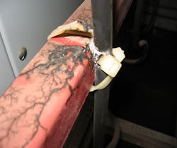
The following images show examples of switchgear degradation, equipment weakness, or deterioration that were identified through an online testing program.
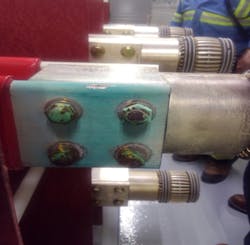
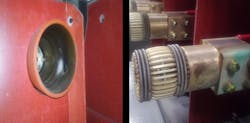
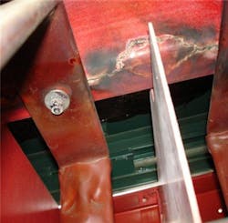
A new 35kV indoor switchgear was damaged by partial discharge as a result of inadequate heaters, high moisture levels, and insufficient clearances (Photo 1). In Photos 2 and 3, you can see signs of partial discharge on the inside of the receiver bottle. This damage aligns with the bolt head/nut from the breaker stab. Photo 4 shows a switchgear insulating barrier board with tracking and deterioration from partial discharge activity.
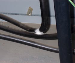
The next two images show damage from medium-voltage (MV) cable degradation. This unshielded MV switchgear jumper cable (Photo 5) does not have sufficient clearance. Over time, it will continue to deteriorate and ultimately fail. Photo 6 shows another example of insulation deterioration, which is being caused by excessive moisture and heat.
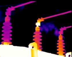
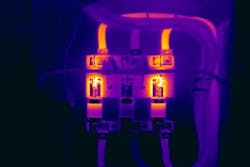
Many of the issues depicted in Photos 1 through 6 were detected during the visual inspection phase of online testing and maintenance activities. But online testing can also reveal underlying issues that cannot be detected during normal visual assessment. For example, the thermographic image of a transformer in Photo 7 shows abnormal heating. This image indicates there may be a connection issue or issues with the fluid and fluid level. Photo 8 shows overheating due to inadequate connections and failing fuses.

Transformer insulating fluids should also be tested to verify its general properties and detect any abnormal gassing that indicates excessive heating or internal arcing. Photo 9 shows a comparison of fluid samples, contaminated versus clean. Transformer fluids are tested for standard quality, moisture content, and dissolved gases. Variations from the standard quality indicate abnormal internal conditions.
Application of online testing and predictive maintenance
Online testing and predictive maintenance services rely on multiple types of technology. An experienced technician will know which technology to use and how to apply it when evaluating each asset (Fig. 1). Let’s run through what tasks a technician would perform during this type of testing process.
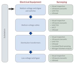
Surveying MV switchgear and switches
The switchgear connects the campus system to the substation. Visual inspections and PD testing will be performed and include ultrasonic, acoustic, UHF, TEV and infrared testing. Switchgear also connects the main arteries of the electrical distribution system. Visual inspections, PD testing, and infrared surveys should be applied to MV switchgear assets (Fig. 2).

Components tested include:
• Switch or fuse disconnects
• Circuit breakers
• Relays
• Auxiliary equipment.
Tests include:
• Visual inspection checks for cleanliness and equipment condition looking for paint/corrosion grounds, corona, abnormal heating, moisture, ground connections, and varmints.
• PD tests rely on various sensors to detect electrical signals generated from deteriorated insulation.
• Detects signals from equipment resulting from deteriorated insulation or defective devices.
• Infrared surveys detect abnormal heating of equipment.
• Sensing heat generation from loose connections and defective surge arresters.
Surveying MV cables
The MV cable are they main arteries of the system and distribute power across campus.
Components tested include:
• Cables
• Cable connections
• Cable accessories (terminations/stress cones, splices)
Tests include (Fig. 3):

• Visual inspection to check for signs of overheating, tracking, ground connections, etc.
• PD tests are used to pinpoint voids, contamination, and improper installation of accessories. Over time, these defects can result in cable or accessory failure if undetected.
• An infrared survey looks for heat buildup and loose connections.
Surveying distribution transformers
A large campus will have multiple distribution transformers supplying a building’s low-voltage electrical system.
Components tested include:
• Transformer exterior
• Gauges
• Insulating fluids
Tests include (Fig. 4):

• A visual inspection checks for cleanliness, obstructions, clearances, insulator condition, fluid levels, fluid leaks, ground connections, gauges and nitrogen pressure.
• An infrared survey looks for loose connections and defective surge arresters.
• Fluid testing and analysis are done to look for contaminants in the insulating fluid and detect gases indicative of heating and arcing.
Surveying LV switchgear
LV switchgear provides power within each building’s electrical infrastructure.
Components tested include:
• Switch or fuse disconnects
• Circuit breakers
• Relays
• Motor controls
• Auxiliary equipment
Tests include (Fig. 5):

• A visual inspection checks for cleanliness and equipment condition of insulators, bushings, gauges, and grounds.
• An acoustic/ultrasonic survey seeks out signals generated from deteriorated insulation.
• An infrared survey looks for heating resulting from loose connections and defective surge arresters.
In conclusion
Historically, many facility managers have used one or more conventional maintenance strategies including time-based maintenance and reliability centered maintenance. Some simply opt for a run-to-failure approach. In today’s business environment of 24/7/365 operations, maintenance strategies are changing. This is causing a trend toward an “as-required” maintenance strategy. An as-required maintenance strategy performs maintenance based on indicators such as results from on-line surveys, operating environment, age and history of asset, service (loading), and criticality of equipment served. This is like a reliability-based maintenance strategy but includes consideration of online survey data.
Most failures of electrical equipment are the result of poor connections or failed insulation. By combining infrared scanning, which identifies poor connections and other
overheating conditions, with partial discharge that detects deteriorated insulation, you minimize the risk of in-service failures. Couple these benefits with fluid analysis of your transformers (one of your most expensive electrical assets) and the trained eyes of an experienced field technician/engineer, and you will see a dramatic reduction in equipment failures and interruptions to service.
The online testing and predictive maintenance services described in this article are meant to complement required offline testing and maintenance and should be part of a facility’s integrated life-cycle management plan. While there are upfront costs associated with online testing and predictive maintenance, the expense is often easily offset by cost savings from optimized offline testing and maintenance, as well as a reduction in emergency services. Most importantly, these services deliver the vital information a facility manager needs to prioritize assets needing attention and avoid wasting resources on equipment that remain in good, reliable condition. Decisions to extend outage schedules can be made without increasing the risk of in-service failures, and budgets can be optimized. The data can also be of value in planning for asset replacements or future system upgrades.
Park brings more than 40 years of experience in the power system industry to his position as director, Engineering and Technical Services for Electrical Reliability Services, Westerville, Ohio. In this role, he provides technical support for such offerings as power system studies and conformity assessment services. He can be reached at [email protected].
SIDEBAR 1: Visual Inspection Basics
A visual inspection is typically performed by a trained field technician or engineer who examines each of the equipment components and looks for any abnormal conditions or indications of possible problems that could lead to equipment failure. A visual inspection check list includes:
• Cleanliness
• Equipment obstructions
• Cracked insulators
• Damaged bushings
• Condition of paint
• Fluid levels
• Fluid leaks
• Fluid/winding temperature gauges
• Nitrogen pressure
• Relay status and targets
• Condition of grounds
SIDEBAR 2: Insulating Fluid Sampling and Analysis
The fluid in a liquid-filled transformer provides a cooling medium to transfer heat from the coils to the radiators and into the air. The fluid also insulates the windings and reduces high-voltage stresses. Eventually, the fluids become contaminated due to heat, insulation deterioration, moisture, air (oxidation), and corrosion. When transformer fluid deteriorates, sludge ultimately forms and coats the windings resulting in decreased cooling capacity and degradation of the solid insulation system.

One of the most effective ways to determine the condition of a liquid-filled transformer is to obtain a fluid sample and perform a laboratory analysis (see Photos).
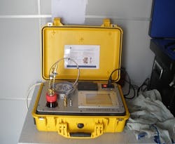
Fluid analysis includes dielectric breakdown, moisture content, color, acidity, interfacial tension, specific gravity, and fluid power factor. Dissolved gas analysis can also be used to identify combustible gases and gases indicative of overheating.
SIDEBAR 3: The Basics of Partial Discharge Testing
Partial discharge (PD) testing involves the use of PD sensors to detect small electrical discharges that occur within or on the surface of the insulation of medium-voltage (MV) electrical assets.
• Results identify assets needing additional attention and/or offline maintenance.
• Trending PD data over time can assist asset managers with strategic decisions regarding the repair or replacement of the assets.
• PD surveys report on the magnitude, location, and type of degradation.
• PD detection is increased through use of multiple PD detection and sensor technologies.
There are a variety of PD testing technologies in the market, including:
• Acoustic sensor
• Ultrasonic sensor
• UHF (ultra-high frequency)/RF sensor
• TEV (transient earth voltage) sensor
• HFCT (high frequency current transformer) sensor

An ultrasonic extension microphone or a directional UHF sensor (Photo A) can be used on indoor metal enclosed MV switchgear. The PD equipment will display signals of interest during this process.

Photo B demonstrates the use of PD equipment and a wireless HFCT transmitter connected to a terminal box for a permanently mounted HFCT sensor monitoring a cable circuit. The HFCT sensor detects PD from the cable providing an early warning of cable deterioration.
A portable ultrasonic dish can also be used to scan for PD signals from various pieces of substation equipment such as bushings, insulators, switches, PTs, and terminations.
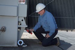
Photo C shows a temporary HFCT and wireless transmitter connected to the tank ground of a transformer. If PD was occurring within the transformer, PD signals would likely be detected on the tank ground. Other sensors such as the acoustic contact sensor could also be used on the transformer tank to detect PD signals from within the tank as well as the ultrasonic and UHF sensors to detect PD emitted from the bushings.
About the Author
Steve Park
Park brings more than 40 years of experience in the power system industry to his position as director, Engineering and Technical Services for Electrical Reliability Services, Westerville, Ohio. In this role, he provides technical support for such offerings as power system studies and conformity assessment services. He can be reached at [email protected].