Circuit Tracing Best Practices

Every electrician has been there: You open a panel, and nothing is marked — or the markings are so outdated, you don’t have confidence in their accuracy. In some cases, you might be able to shut off the main breaker and use trial and error to troubleshoot. But what about those times when a total loss of power isn’t an option? Health care facilities, hospitals, and data centers are just a few businesses where power shutdowns simply aren’t acceptable.
Tracing circuits and locating breakers is the ultimate test of an electrician’s patience. You not only need the right tools for tracing, but you also need to trust that those tools will deliver accurate and reliable reads. Using circuit tracing equipment properly and fully understanding what it can do will give you the confidence needed to locate electrical paths throughout a facility when circuit groupings are unclear or some panels can’t be found. Here’s the process we suggest for getting the most out of your circuit tracers.
Get the right tool for the job
Every circuit tracer has a specific voltage rating, so make sure you know the voltage limit for the brand and model you are using. When using any circuit tracer, it is important to review the instruction manual before operation. There are different features packed into these tools to provide you with the ability to trace circuits, locate breakers, or detect faults in the line, so make sure to become familiar with the features and use instructions first.
Understanding category ratings is also important. You will want to make sure you select tools that meet the International Electrotechnical Commission (IEC) standards for electrical test and measurement equipment to assure the device will help protect you from the risks of shock caused by transient high-voltage spikes in electrical distribution systems. The IEC has established a standard for test and measurement equipment overvoltage protection capacities. These established overvoltage protections can be further divided into categories. Wherever you need overvoltage protection, you should choose at least the minimum category rating appropriate to the type of work you expect to be doing. Categories include:
- Measurement Category I (CAT I) — is for measurements performed on low-voltage circuits not directly connected to main circuit breakers.
- Measurement Category II (CAT II) — is for measurements performed on fixed or non-fixed local level power devices like household lighting, appliances, or office equipment. Category II equipment may also be used in Category I applications.
- Measurement Category III (CAT III) — is for measurements performed at the distribution level on equipment like primary feeders or branch circuits. These circuits are usually separated from Category IV (whether utility service or other high-voltage sources) by a minimum of one level of transformer isolation. Category III may also be used in Category II and Category I applications.
- Measurement Category IV (CAT IV) — is for measurements performed at the primary or utility supply level. Category IV may also be used in Category III, Category II, and Category I applications.
Another important consideration is the radial asymmetry (signal sensing) ability of the receiver when tracing live lines. Most circuit tracers receive signals using a single axis sensor, which can make tracing hidden wires more challenging if they are not run in a vertical or horizontal direction — or if there are multiple devices along the wire run. Models are available that use two-axis sensing, omnidirectional sensing, or a rotating user interface (screen). This makes tracing hidden wires easier and also allows the receiver itself to be held in a vertical or horizontal orientation.
Set up the transmitter
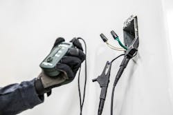
This setup is dependent on what you’re looking for. If you are tracing conduit, data cable, or coaxial cables, use alligator clips to make a connection, while making sure you have a good ground. If possible, ground the far end of the conductor for better results. For most live breakers or tracing of GFCI-protected circuits, you will simply plug the transmitter into the outlet in question. You can still use proper leads if an outlet is not available (Figure).
Power up the receiver
Before powering up, if possible, remove any gloves you’re wearing. The hand and body act as a ground plane for the receiver, so this will improve the sensitivity. Confirm that the receiver is picking up a signal from the transmitter. Different units will confirm this signal in different ways.
Select your mode
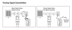
Most tracer units have both a “search” and “breaker” mode; using both modes can help you pinpoint the line you’re looking for. Use “search” to begin your trace because this mode can detect a wider signal range. Then switch to “breaker” mode for a more precise reading. The receiver will block out weaker signals, allowing you to observe small changes in signal strength. This will help you pinpoint the correct breaker, trace circuits of objects that are very close to the receiver, and determine the exact locations of a break or short in a conductor.
Scan the panel and breakers
Once you are on the panel and ready to find the proper breaker, a best practice is to scan the panel and breakers. Start by running the receiver in a counterclockwise manner around the outside board of the panel, then up and down the panel cover. This will locate the correct panel when there are several to choose from.
Pro Tip: Panel trim can distort the signal when locating breakers on the outside corners of the panel. If you think that you are not receiving consistent readings, remove the trim, if possible.
Next, scan each row of breakers from top to bottom. Once you have what you believe to be the correct breaker, make a small counterclockwise rotation around it versus the breakers next to it. The signal strength will confirm you’ve located the proper breaker for your line.
Circuit tracers are an incredibly useful tool for electricians – helping them trace with confidence. Proper use will help assure that users locate and trace the correct line every time, no matter the situation.
J.C. Tiller is the North Texas territory manager for Greenlee, a part of Emerson’s Professional Tools portfolio. He can be reached at [email protected].
About the Author
J.C. Tiller
J.C. Tiller is the North Texas territory manager for Greenlee, a part of Emerson’s Professional Tools portfolio.