Working Safely With Circuit Breakers
Large circuit breakers in service today at industrial and commercial facilities come in many shapes, sizes, configurations, and voltage ratings — with the primary purpose of protecting electrical power circuits 24 hours a day, seven days a week. Understanding the types (and more importantly the risks) of these watchdogs of the industry is essential for electrical professionals.
There are several types of operating styles, differentiated by what medium they use to safely extinguish an arc in an electrical power circuit; including air, air-magnetic, vacuum, and SF6. While most older circuit breakers were manufactured in the United States, mostly by companies such as Westinghouse Electric, General Electric, and Federal Pacific, today many of the circuit breakers are imported from outside of the United States. And while the older circuit breaker manufacturers may have merged with others, were bought out, or might have simply gone out of business due to competition… a large portion of their products are still in use today. The good news is that the operation of these older units (and newer ones currently in production) is similar. That reduces the risk.
Air and air-magnetic circuit breakers are commonly molded-case, insulated-case, and low-voltage power circuit breakers. They use arc chutes to extinguish the arc — nothing fancy, but they have become more sophisticated through the years. Large metal-framed low-voltage power circuit breakers (LVPCBs), once the workhorse of the industrial sector, are not as common as they once were, likely due to cost and the maintenance required.
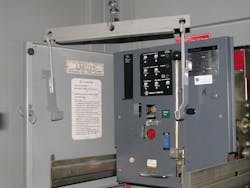
While LVPCBs were the industry standard for years (Photo 1) and insulated-case circuit breakers have, for the most part, taken their place in the industry, there are still thousands of LVPCBs still in operation. You need to understand their operation and maintenance requirements if you encounter them in the field.

NFPA 70E Requirements
The first task involved when working on a circuit breaker is to take it out of service and tackle the necessary paperwork. Many technicians dislike paperwork, but it serves its purpose to promote safety if it’s completed properly. Remember that NFPA 70E supplies the minimum requirements, not the best practices. Article 110 includes several requirements for circuit breaker operation, although it focuses on the electrical safety program.
Everything in Art. 110 is from the 2021 edition of NFPA 70E. Beginning with Sec. 110.5(C) [Condition of Maintenance], safe work practices are presented in Sec. 110.5(D) [Awareness and Self-Discipline], Sec. 110.5(H) [Risk Assessment Procedure], Sec. 110.5(H)(2) [Human Error], Sec. 110.5(H)(3) [Hierarchy of Risk Control Methods], Sec. 110.5(I) [Job Safety Planning and Job Briefing], Sec. 110.5(K) [Electrically Safe Work Condition Policy], and Sec. 110.5(L) [Lockout/Tagout Program]. Sections throughout 70E explain each of these electrical safety program requirements, but that’s for another article and another day.
The Job Safety Plan
The first step when working on a circuit breaker is to complete a job safety plan, where all steps are planned out and recorded. There are good reasons for this step:
- A job safety plan forces you to reason out what needs to be done: What equipment is needed? What steps will be followed as the task is performed? What personal protective equipment (PPE) may be needed? And what condition is the equipment in?
- It allows a second qualified person to read over the job safety plan and verify that it is accurate, safely doable, and complete.
Perform a Risk Evaluation
The next step is to evaluate the risk and determine which risk control methods are needed. People tend to underplay this step, but it has tremendous importance. NFPA 70E defines risk as “a combination of the likelihood of occurrence of injury or damage to health and the severity of injury or damage to health that results from a hazard.” The goal is to reduce the likelihood of an incident as much as possible.
The risk of a task cannot be driven to zero unless the equipment is placed into an electrically safe work condition by de-energizing the entire circuit. This may not be convenient for many reasons, but it may be possible during a facility’s maintenance or emergency shutdown, after normal work hours, or during the weekend. Turning off a circuit breaker before performing any task on it should always be what you do.
OSHA regulation 1910.333(a)(1) states: “Live parts to which an employee may be exposed shall be de-energized before an employee works on or near them, …” To avoid this requirement of being exposed to live parts, the employee must be removed from the area of danger, such as by using remote operating devices or remote racking devices, wearing the proper arc-rated clothing and PPE, or other methods provided by 70E. Some circuit breakers are just not safe to operate with just the use of PPE, so remote devices are needed. Again, it’s up to you to assess the risk and make that determination.
Risk Factors
When working with circuit breakers, risk increases with higher voltages, higher ampacities, higher fault currents, longer tripping delays (such as short time delay), and unknown operating conditions (e.g., past-due maintenance intervals, repeated misoperation).
At some point, those contribution factors of increased risk may require the bus to be de-energized. As an example, opening and resetting a tripped 20A molded-case circuit breaker (MCCB) in your house would likely not require any special steps. Ramp that up to a 1,000A MCCB, and the risk increases substantially. PPE may be necessary due to the current rating of the circuit breaker, even though it is not specifically required in 70E. Determining the risk involved in operating that circuit breaker must be made by the worker in the field, as they are encountering factors the 70E Committee cannot foresee or codify.
With medium-voltage circuit breakers and older, draw-out low-voltage power circuit breakers. The risk can increase greatly because the voltage is higher (except for the LVPCB), the current being handled is usually greater, there is no built-in overcurrent device in a medium-voltage breaker, and they tend to run slower. For example, molded-case and insulated-case circuit breakers typically open in 1.5 to three cycles; in the current-limiting type of MCCBs, that time drops to 0.5 cycles. Medium-voltage circuit breakers typically open in three to eight cycles, plus the operating time for protective relaying. LVPCBs open in about four cycles. These are their respective “instantaneous” operating times.
If an incident energy analysis has been performed, higher incident energy indicates greater risk. This is due not only to the incident energy exposures but also to the increased risk of arc blasts at higher incident energies. This is why the 70E Committee deleted the informational note that indicated 40 cal/cm2 was a maximum exposure level. While that is not what it stated, that is the way it was being interpreted by users of 70E. If the overcurrent device, such as the circuit breaker, was not maintained properly and its lubricants began to dry out, its operating time would increase. How much would it increase? There’s no way to tell. In an arc flash, time is critical, as incident energy is proportional to opening time. Double the opening time, and the incident energy is doubled.
Another risk factor is human error. It may be someone else’s human error, not yours. It’s necessary to list all things human error could cause and what the result of each error would be. Unfortunately, people tend to make errors. It’s not that they want to, but distractions, sleepiness, multi-tasking (people have a tendency to think they excel at this, which may not be true), performing the task incorrectly (what doesn’t injure or kill us becomes our way to do things), or dropping a tool, just to name a few, could cause an incident. It’s like getting on a roller coaster: Once the ride starts, there’s no getting off. Once an incident begins, there’s no stopping it until it’s over.
Reducing the risk
Tools are available that can help reduce the risk.
Lifting Winch
Technicians often overlook using a winch to lower the circuit breaker from its cubicle. This accessory is provided on many draw-out LVPCB installations, and it is convenient if appropriately used. Understand the proper maintenance, operation, and limitations of lifting winch assemblies before using them.
Photo 2 shows a winch as it is typically found. Looks ready to go, doesn’t it? It is, but not the way one would think. Notice anything wrong with the cable? Each winding of the cable is overlapping the one underneath. It looks innocent, but add the weight of a circuit breaker, and it becomes hazardous.
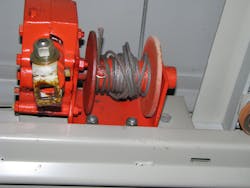
As the cable unwinds, it can pop or snap, causing the circuit breaker to bounce — and often it bounces hard. Beyond the physical shock (if there’s any weakness in the cable) it could snap, letting the circuit breaker fall where it may. Trying to stop an LVPCB from falling would crush Superman, and it happens fast.
A simple fix is to take just a few minutes to unwind the cable from the reel and wind it back while pulling on it slightly so it is straight on the reel. The cable cannot be let loose until it is connected to the circuit breaker’s lifting bars.
Circuit Breaker Lifting Bars
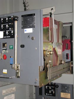
Photo 3a shows the lifting bars from one manufacturer, but they are all similar in the way they work. Photo 3b shows a typical LVPCB ready to be lowered properly by lifting it off its extension arms. The circuit breaker rollers must be checked before they are rolled out of their cubicle to verify they are on the extension arms and attached properly to the circuit breaker. The cable is just out of sight in Photo 3b. It has been unwound from its reel and rewound, so it is straight — and any wound cable does not overlap.
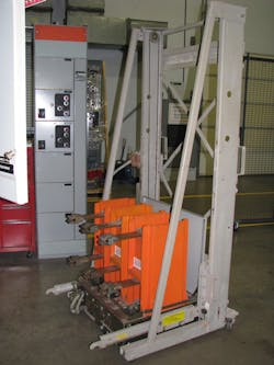
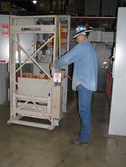
Lift Platform
It’s no fun seeing a circuit breaker hit the floor. If no cable mechanism is available, a hydraulic lift or mechanical lift platform can help you prevent this from happening. As Photo 4a and Photo 4b show, many medium-voltage manufacturers supply such a lift to install and remove their equipment. The equipment is de-energized, and the technician is wearing the correct PPE for this task.
Remote Operating and Racking Devices
Photo 5 and Photo 6 illustrate why a remote operating device and a remote racking device should be used when operating and racking a draw out circuit breaker while it is energized. Photo 5 shows that the arms of the bus connectors are out of alignment on this medium-voltage vacuum circuit breaker. If gone undetected — and the breaker is racked in locally by a person in front of the unit — a failure could cause injury to the operator performing the task.
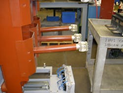
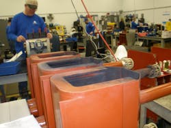
Photo 6 (the same circuit breaker) shows the results of a vacuum bottle failure, probably due to a racking incident. Any type of draw-out circuit breaker can fail when the circuit breaker bus connection makes inadvertent contact with the bus. There’s no time to get out of the way. Remember the roller coaster analogy.
Circuit breakers can also fail from being operated (i.e., racking them in or out of an enclosure). Photo 7 shows a bent racking gear pin from a low-voltage draw-out power circuit breaker. Superman must have found his calling when he racked this circuit breaker. As a result of this abuse, if the pin had sheared off, the circuit breaker would not stop where it should have at the fully connected position; it would continue to move past that position and begin to rack out again. That’s amazing and dangerous, as it would break contact if the technician kept racking.
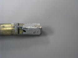
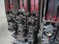
Photo 8 shows a medium-voltage air-magnetic circuit breaker. Note the light bulb on top of the contacts. This is not uncommon; foreign objects such as tools or maintenance items are often left on circuit breaker assemblies, which is why a visual inspection is important. Note also how the contact clusters have fallen apart, causing the circuit breaker to fault. This is likely due to improper lubrication of the contact clusters, which is a good indication no maintenance had been performed on either of the circuit breakers.
Conclusion
Operating and racking circuit breakers should be done with care as well as the proper equipment and PPE. Understanding pertinent NFPA 70E requirements that apply to any task that could cause injury or even death is the first step in a good safety plan. As we’ve shown above, the consequences of not following accepted industry safety practices and/or neglecting equipment maintenance can result in damaged or destroyed equipment.
As qualified electrical workers in the field, take special care when performing tasks that could cause an incident. Remember the roller coaster analogy: Once it begins, there’s no stopping it.
Author’s Note: This article was originally written by James R. “Jim” White of Shermco Industries. We have taken Jim’s work, updated it, and offered this revision in Jim’s honor. Great job, Jimbo!
Ron Widup Industries is the vice chairman, board of directors, and senior advisor of technical services for Shermco Industries and has been with Shermco since 1983. He is a member of the NETA Board of Directors and Standards Review Council; Principal member of the Technical Committee for NFPA Standard for Electrical Safety in the Workplace (NFPA 70E); Principal member of the National Electrical Code (NFPA 70) Code Panel 11; Principal member and Chairman of the Technical Committee for Standard for Competency of Third-Party Evaluation Bodies (NFPA 790); Principal member and Chairman of the Technical Committee on Recommended Practice and Procedures for Unlabeled Electrical Equipment Evaluation (NFPA 791), member of the Technical Committee Recommended Practice for Electrical Equipment Maintenance (NFPA 70B). He is a member of the Texas State Technical College System (TSTC) Board of Regents, a NETA Certified Level 4 Senior Test Technician, a State of Texas Journeyman Electrician, a member of the IEEE Standards Association, an Inspector Member of the International Association of Electrical Inspectors, and an NFPA Certified Electrical Safety Compliance Professional (CESCP).
Electrical Testing Education articles are provided by the InterNational Electrical Testing Association (NETA), www.NETAworld.org. NETA was formed in 1972 to establish uniform testing procedures for electrical equipment and systems. Today the association accredits electrical testing companies; certifies electrical testing technicians; publishes the ANSI/NETA Standards for Acceptance Testing, Maintenance Testing, Commissioning, and the Certification of Electrical Test Technicians; and provides training through its annual PowerTest Conference and library of educational resources.
About the Author

Ron Widup
Sr. Advisor, Technical Services
Ron Widup is the vice chairman, board of directors, and senior advisor of technical services for Shermco Industries and has been with Shermco since 1983. He is a member of the NETA Board of Directors and Standards Review Council; Principal member of the Technical Committee for NFPA Standard for Electrical Safety in the Workplace (NFPA 70E); Principal member of the National Electrical Code (NFPA 70) Code Panel 11; Principal member and Chairman of the Technical Committee for Standard for Competency of Third-Party Evaluation Bodies (NFPA 790); Principal member and Chairman of the Technical Committee on Recommended Practice and Procedures for Unlabeled Electrical Equipment Evaluation (NFPA 791); and Principal member of the Technical Committee Standard for Electrical Equipment Maintenance (NFPA 70B). He is a member of the Texas State Technical College System (TSTC) Board of Regents, a NETA Certified Level 4 Senior Test Technician, a State of Texas Journeyman Electrician, a member of the IEEE Standards Association, an Inspector Member of the International Association of Electrical Inspectors, and an NFPA Certified Electrical Safety Compliance Professional (CESCP).