Proper Testing Techniques When Using a Time Domain Reflectometer

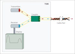
A time domain reflectometer (TDR) measures reflections along a cable. It is similar in principle to radar. To measure those reflections, the TDR transmits an incident signal into the cable and watches for its reflections (Fig. 1). If the cable has a uniform impedance and is properly terminated, there will be no reflections — and the remaining incident signal will be absorbed by the termination at the far end. However, if impedance variations exist, some of the incident signals will be reflected to the source.
Basic principles
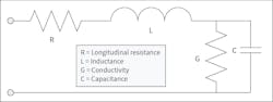
Two side-by-side conductors separated by an insulator (as in a cable) will show characteristic impedance between them. If the distance between the conductors does not change, the impedance does not change. If the distance between them increases, the impedance goes up. If the distance between them decreases, the impedance goes down. Time domain reflectometers (TDRs) use simple transmission-line theory and pulse-reflection principles to detect these impedance changes along a cable. The TDR transmits high-frequency electrical pulses that travel through the cable until a change in characteristic impedance is encountered (Fig. 2). Depending on the nature of the impedance change, all or part of the transmitted pulse will reflect to the TDR.
A change in a cable’s characteristic impedance will cause one of two types of reflections: positive or negative.
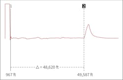
- Positive reflections are caused by increases in impedance (Fig. 3). This will occur if the longitudinal resistance were to increase or if the conductors go farther apart, causing an inductive change.
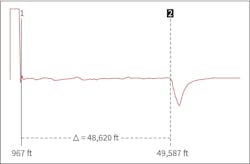
- Negative reflections are caused by decreases in impedance (Fig. 4). This will occur if the conductance and/or capacitance change as the conductors get closer together, causing a capacitive change.
A TDR translates reflections into traces that can be interpreted to indicate events, such as open circuits, short circuits, and splices in the cable circuit. All traces follow the two basic rules of impedance changes.
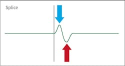
Let’s review the TDR pattern for a common cable splice (Fig. 5). As the TDR pulse enters the splice and the conductor and metallic shield are separated, an inductive change in the characteristic impedance is seen. This results in a small positive reflection. As the TDR pulse exits the splice, the conductor and metallic shield come back to their natural separation, resulting in a capacitive change. This transition results in a small negative reflection.
Reading a TDR signature is like reading a map. Before reading a map, however, you must learn what the symbols mean. Before reading a TDR trace, you must first understand the reflection patterns.
Making measurements
Understanding the basics is beneficial, but to be helpful, you also need to know the location of these changes in the cable. A TDR sends pulses along the cable that are reflected when they encounter a change in impedance. The TDR notes how long it takes for the transmitted pulse to travel along the cable and for the reflections to return to the unit. If the TDR knows how long the pulse has been gone and how long it has been traveling, it can determine the distance.
TDRs are like an arithmetic word problem that asks: “If you leave Dallas and travel for two and a half hours at 50 miles per hour, how far have you gone?” Because the TDR knows how long the pulse has been gone, if we can tell it how fast these pulses and their reflections travel along the cable, it will be able to calculate the distance from the TDR to the impedance change. We can do this. But to complicate the situation, the TDR’s pulse travels at different speeds in different types of cables.
The transmitted pulses travel at different velocities on different cables — much like a ball travels at different velocities through liquids with different viscosities. The velocity of propagation changes according to these factors:
- Impedance
- Dielectric materials (e.g., XLPE, PVC, PILC, EPR)
- Age of the cable
- Temperature
- Moisture content (i.e., water inside the cable)
- Wire position inside the cable (e.g., communication type cables)
- Cable manufacturer (composition of insulation material and additives)
Fortunately, we can tell the TDR how fast the pulses and their reflections travel in various cables. This speed is usually stated as a ratio of the speed of the pulse in the cable divided by the speed of light in a vacuum. This ratio is called the velocity of propagation (VoP). If the VoP is 0.50, the speed of the pulse is 50% of the speed of light in a vacuum or
0.5 x 186,000 miles per second. Examples of VoPs by cable type are shown in the Table below.

If velocity is not known, the velocity of a cable can easily be determined by connecting it to a sample cable of known length. If we can see the length markings or measure it, we can work backward with a TDR and calculate the VoP.
The TDR now has enough information to calculate the location of the event. Like our trip from Dallas, it knows how long the pulse and its reflection traveled, and it knows how fast that pulse was going. The TDR must merely do the arithmetic.
If neither the velocity nor the length of the cable is known, an accurate location can be accomplished by measuring the distance to the fault from both ends of the cable. If an error exists in the velocity setting, the TDR will over-measure or under-measure from both ends of the cable. The fault will be between the two measurements.
Theory into practice
- A TDR will not work on a single conductor. The TDR relies on the impedance model of two conductors in parallel.
- TDR pulses do not travel down the conductor and return on the neutral. TDR pulses travel down the conductors and reflect in those conductors.
Think of the TDR pulse as a train and the cable as train tracks. The train requires two tracks (rails) to function; the TDR pulse requires two conductors. If one rail is missing, the train must stop; if one conductor becomes open, the TDR pulse cannot travel any farther. If a rail is missing, the train may need to return to the station and will take the same path, but travel backward; if a conductor is open, the TDR pulse cannot continue and will reflect to the source.
Applications
Communication cable
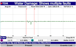
For telephone and CATV applications, water can seep through the insulation of a twisted-pair cable at multiple points. In these situations, testing the cable from both ends and recording the distance to a fault provides the tester with an accurate assessment of the severity of the water issue (Fig. 6) or confirms that the anomaly that was initially spotted is correct.
Electrical cable
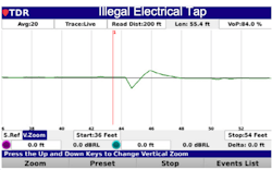
Illegal electrical service taps are a major problem for many electric companies throughout the world. An illegal tap occurs when an individual connects to the power cable before it reaches the meter. If you bypass a meter, you’re stealing electricity from the utility. Millions of dollars are lost due to theft of service. A TDR can be useful in identifying the location of illegal taps (Fig. 7) and removing them from the system.
Low-voltage electrical cable
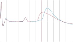
The best methods for locating a fault on a low-voltage electrical circuit involve a good vs. bad comparison (Fig. 8). A healthy TDR trace produced by a complex network shows many reflections caused by the service connection taps and the ends of these cables. Even a gross fault down the network will be masked by other features of the network. In many cases, comparison and differential techniques are the only option.
Medium-voltage electrical cable
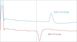
The arc reflection method of pre-locating a fault on medium-voltage electrical cables combines the use of a TDR and a surge generator (i.e., “thumper”). By using an arc reflection filter, a low-voltage TDR and a high-voltage surge generator connected to the faulted cable, the TDR can look down the cable while surging (i.e., thumping). The filter protects the TDR from the surge generator’s high-voltage pulses and routes the low-voltage pulses down the cable. When an arc is created at the fault location, its resistance is reduced to a very low value (less than 200 ohms), which will reflect TDR pulses. The arc location will appear as a downward reflection — a short circuit — on the TDR cable trace (Fig. 9).
Summary
The TDR is a versatile, low-voltage device that can be used on almost any cable structure, provided two conductors are traveling in parallel. The TDR creates a map of the cable displaying impedance changes or events that occur along the transmission path. Distances to events can be determined by knowing the travel time between the launch of the incident pulse and any reflected pulses, and the speed or velocity at which the pulses are traveling. Pulse width settings determine how far pulses can travel and reflect along a cable. They also identify a dead zone or closely spaced events.
About the Author

Thomas Sandri
Thomas Sandri is the Director of Workforce Development at Vector Power, where his responsibilities include designing and developing learning courses. He has been actively involved in the fields of electrical power and telecommunications for over 40 years. During his career, Tom has developed numerous training aids and courses, been published in various industry guides, and conducted seminars both domestically and internationally. Thomas supports a wide range of electrical and telecommunication maintenance application disciplines. He has been directly involved with and supported test and measurement applications for over 35 years. He is considered an authority in application disciplines, including insulation system analysis, medium- and high-voltage cable testing, and partial discharge analysis, as well as testing and maintenance of battery and DC systems. Tom received a BSEE from Thomas Edison University in Trenton, New Jersey.