Electrical Signature Analysis of Oil- and Dry-Type Transformers
Key Highlights
- Electrica signature analysis (ESA) uses the magnetic field in the air gap of an electrical machine to evaluate power quality conditions.
- Dry and oil transofrmer types are subject to problems associated with power quality, loose connections, cooling medium issues, and other conditions associated with loads and the environment.
- Using ESA for transformers provides an additional level of fault detection, especially when used for continuous monitoring.
- ESA is an excellent tool for direct or incidental detection of major defects in transformers by evaluating the power quality, phase impedance, and impact of loads.
Periodic and continuous electrical signature analysis can be used to evaluate the general condition and power quality that affects oil- and dry-type transformers. This article discusses how conditions such as loose connections, resonance, component looseness, and failing electrical components can be detected. Case studies from several applications, including wind power, solar, and industrial dry- and oil-type transformers, are presented.
Defining electrical signature analysis
The purpose of electrical signature analysis (ESA) is to use the magnetic field in the air gap of an electrical machine to evaluate power quality — the condition of the electrical and mechanical components in the electric motor or generator and driven equipment. The analysis is performed using measured voltage and current data with the line frequency acting as the amplitude-modulated carrier frequency.
Sample rates, FMAX, bin size, and Nyquist are similar to those of vibration analysis with a Nyquist value of 2 and the data being analyzed in an FFT spectrum in either linear data or decibels. Decibel levels are read down from the peak voltage or current to associated peaks and are presented as -dB (or dB down). Unlike in vibration, where a value such as stator conditions is the number of stator slots times the running speed, ESA is the number of stator slots times the RPM +/- of the line frequency.
In the case of electric machines, most conditions (and the forcing functions associated with them) are interpreted directly from the supplied data. This means that a defect in a bearing, rotor, or stator is explicit, while the use of the technology and measurements of a transformer’s electrical signature are implicit and infer conditions associated with condition and reliability. With transformers, we review phase impedance, power factor, phase balance, harmonics, and variations in the magnetic field between primary and secondary.
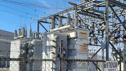
In oil-filled transformers, the pass-through connections go through insulated seals referred to as bushings that seal the oil in. These are often oil-filled and hold the external connections away from the transformer frame (Photo 1). The fins on the sides are radiators for cooling the transformer oil, which normally relies upon thermal flow. Fans may be applied to extend the operating range of the transformer. Large sealed transformers may also include an expansion tank for excess oil as it expands thermally. There may also be pressurized nitrogen and nitrogen bottles to keep dissolved gases in the transformer oil and protect the insulation system and oil from water. Transmission and distribution systems, as well as some large substation transformers, may also have auto-taps that adjust for voltage to keep the output within an acceptable range.
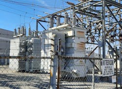
The primary difference between an oil-type and a dry-type transformer is the cooling medium and resulting size. Dry-type transformers (Photo 2) use air as the cooling medium. Both transformer types require slightly different maintenance tasks and have slightly different failure modes. In oil-type transformers, the cooling medium can accelerate reliability issues through degradation from soluble gases generated from age, contamination, heat, and operation. Dry-type transformers are subject to contamination and problems with airflow.
Dry and oil transformer types are subject to problems associated with power quality, loose connections, cooling medium issues, and other conditions associated with loads and the environment. Several existing technologies are used for different voltage levels and fault types. These are normally passive or injected technologies, such as turn-to-turn ratio testing, oil analysis, ultrasound, vibration analysis, partial discharge testing, insulation resistance, and others. Many papers and articles associated with using electrical signature analysis and power quality testing are available. This article will focus on the types of issues associated with ESA fault detection in transformers.
Using ESA for transformers provides an additional level of fault detection, especially when used for continuous monitoring. Conditions covered in this include:
- Power quality, including power factor and harmonics
- Core excitation in wind power applications
- Load balancing in solar applications
- 13.8kV to 480V transformer overload due to ground/neutral harmonic content
- Loose connections on the transformer bushing
During an electrical reliability evaluation of a food processing site, it was noted that the main transformer supplying the facility had a tinny ring to it. Evaluation of the subtransformers fed from the main transformer, observation of the main transformer heating on a 34°F day while operating at a measured 70% load, and a plant power factor under 0.8 indicated that the main transformer was overloaded, and the harmonic level and power factor were outside of its operating capabilities.
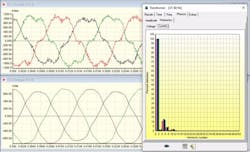
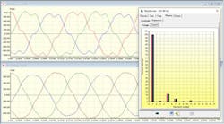
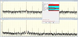
Figure 1 shows the voltage and current waveforms at the primary side of one of the subtransformers. Figure 2 shows the current on the grounding conductor between the subtransformer and main transformer. Each of the subtransformers adds to the power factor, harmonic level, and ground/neutral loads at the electric utility feed.

The harmonic content shows up in the power signal and ground path back to the main transformer. Poor power factor adds to core heating and the overall transformer’s effective load. The 70% load quoted from the electric utility is based upon the apparent load and does not include derating and core resonance due to poor power factor and harmonic content.
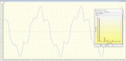
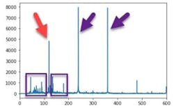
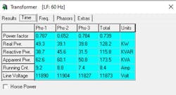
Due to access restrictions, smartphone audio was obtained and processed to show power loss (Fig. 3) and decibel patterns (Fig. 4). The purple squares in Fig. 6 are related to loose components, and the red arrow points to core vibration due to harmonics and high ground currents. Figure 7 shows the power factor and core vibration (refer to IEEE Std. C57.136-2000, IEEE Guide for Sound Level Abatement and Determination for Liquid-Immersed Power Transformers and Shunt Reactors Rated over 500kVA). The poor power quality conditions will reduce the life of the transformer.
Core excitation in wind power
A common problem in the wind industry is overheating transformers due to a combination of factors, including the firing frequency of rotor inverters in doubly fed induction generators (DFIG). The factors that generate this issue are outside the scope of this article. However, the conditions are easily detectable with ESA, including detection of the inverter frequency and a transformer excitation frequency that falls between the first and second inverter harmonic.
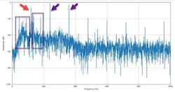
The frequencies (Fig. 5) generate heating in the transformer core and will generally increase thermal gassing, depending on the dielectric oil, which primarily consists of hydrogen. Thermal and chemical degradation of the insulating materials inside the transformer may result. In dry-type transformers, resonance will also affect connections.
13.8kV to 480V overload due to ground/neutral harmonic content
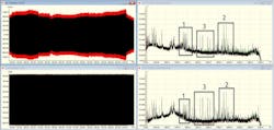
The ground and neutral feedback to the transformer will generate heating and increase the loading on the transformer in cases where voltage and current are present, in particular where there are harmonics over the fundamental.
Note the changes between Fig. 6 and Fig. 7 — where neutral and ground harmonic correction was implemented. The noise in the current waveform decreases, and the even harmonics are eliminated due to a reduction in load on the transformer core. The comparison is at a similar load current.
Loose connection on transformer bushing
Loose connections (Fig. 8) are found through a combination of impedance unbalance; even harmonics will often be present. The impedance unbalance (Fig. 9) distinguishes between harmonic loading and the loose connection.
Conclusion
ESA is an excellent tool for direct or incidental detection of major defects in transformers by evaluating the power quality, phase impedance, and impact of loads. In these examples, we have detected loose connections, overloading, neutral and ground impacts, power factor problems, and a few others. When used as part of continuous monitoring, these conditions can be found early enough to mitigate the defects.
Electrical Testing Education articles are provided by the InterNational Electrical
Testing Association (NETA), www.NETAworld.org. NETA was formed in 1972 to establish uniform testing procedures for electrical equipment and systems. Today the association accredits electrical testing companies; certifies electrical testing technicians; publishes the ANSI/NETA Standards for Acceptance Testing, Maintenance Testing, Commissioning, and the Certification of Electrical Test Technicians; and provides training through its annual conferences (PowerTest and EPIC — Electrical Power Innovations Conference) and its expansive library of educational resources.
About the Author

Howard W. Penrose, PhD, CMRP, CEM®
Howard W. Penrose, PhD, CMRP, CEM® is president of MotorDoc® LLC, a veteran-owned small business. He was a U.S. Navy electric machine repair/rewind journeyman (NEC 4619/4621) and is the 2022-2025 chair of standards development at American Clean Power. Penrose is the past chair of the Society for Maintenance & Reliability Professionals (SMRP); past chair of Chicago Section IEEE; an active member of IEEE standards committee(s); and past Senior Research Engineer at the University of Chicago Energy Resources Center. He is a five-time recipient of the UAW-GM People Make Quality Happen Award, a leading researcher of ESA/MCSA applications, and has worked with diverse design teams, including the GM hybrid Tahoe and Volt, John Deere 644 and 944 hybrid construction tractors, LVAD heart pump, flywheel generators, and high temperature/low atmosphere electric machines. He serves on the SMRP government affairs team for workforce, smart grid, cybersecurity, and infrastructure, among numerous other energy/environment/ workforce programs. Penrose received his PhD in industrial-general engineering and is certified in data science and machine learning from Kansas Western University, Stanford University, the University of Michigan, IBM, and AWS.