Insulation Resistance Testing Best Practices
Key Takeaways
- Understand and comply with relevant codes and standards such as NFPA 70B, NFPA 79, and NEC 110.7 to ensure proper insulation testing procedures.
- Develop a comprehensive job safety plan that includes lockout/tagout, PPE, and clear procedures to protect personnel during testing.
- Regularly inspect and calibrate test equipment, select appropriate test voltages, and perform spot readings to accurately assess insulation condition.
- Correct insulation resistance measurements for temperature and humidity variations, and monitor trends over time to detect degradation early.
- Use advanced tests like dielectric absorption ratio (DAR) and polarization index (PI) to identify moisture or dirt in insulation and prevent failures.

Electrical insulation failure is a common cause of downtime, rework, equipment damage, and fire. In fact, a recent NFPA study found that the largest contributor to home electrical fires and fatalities came from electrical distribution equipment and lighting failures. Insulation breakdown can be detrimental, but its quality can be monitored by following best practices for insulation resistance testing. Electrical professionals must know the requirements, recognize the hazards, understand the process, and use written procedures to reduce equipment issues and incidents. Let’s take a look at some best practices that will ensure better outcomes.
#1 Know the Requirements
Various codes and standards require insulation resistance testing for safety. NFPA 70B, Standard for Electrical Equipment Maintenance, the Health Care Facilities Code, and NFPA 79, Electrical Standard for Industrial Machinery, are examples of documents requiring insulation testing. Section 110.7 [Wiring Integrity] of the NEC requires that completed wiring installations be free from short circuits and ground faults. Complying with this Code section and other documents requires insulation resistance testing.
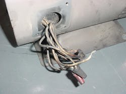
Insulation resistance testing is performed using specially designed test equipment to apply a DC voltage at a potential near the rating of the insulation and measure any current that leaks through the insulation. Insulation degrades over time and will gradually begin to leak more current into conduits and enclosures, possibly resulting in catastrophic failure of equipment if left unchecked (Photo 1).
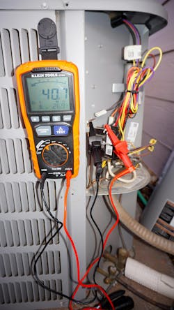
As with all electrical work, insulation resistance measurements must be performed by qualified persons — those who have been specially trained and demonstrated their skills and knowledge in the construction of the unit under test and the operation of the test equipment. An important component of qualifications is to recognize the hazards of performing these tests and the procedures to follow to avoid injury to oneself or others (Photo 2).
#2 Complete a Job Safety Plan
Unquestionably, the most assured method of achieving safety when measuring insulation resistance is to complete a written job safety plan before work begins. Measurements are conducted at voltage levels from 250VDC to 5,000VDC. Current values are low but cannot be ignored. Contact with these hazards can result in painful to severe shock and burn injuries. While modern test sets have built-in protection, attempting to measure insulation resistance by applying voltage to an already energized circuit can be especially dangerous. Therefore, job safety planning must include lockout/tagout requirements for the item under test, identify the test voltages and specific test equipment to be used, the limited approach boundaries for shock protection, any needed PPE (voltage-rated rubber goods), and any specific company procedures for conducting resistance testing.
An important consideration is protecting other personnel from electric shock. A shock potential exists not just at the point where test leads are applied, but also at downstream wiring, machinery, cable runs, conduit, cable trays, and wireways. All of these components and machinery have the potential to be energized when a test is performed. Large areas may be prohibited from access when performing insulation resistance testing.
#3 Select and Inspect Test Equipment
Insulation resistance test equipment, including test leads, must be inspected before each use. Without charged batteries, the proper output test voltage may not be achieved. The physical condition of the tester and leads must ensure no danger of electric shock to test operators. Calibration is generally required every 12 months, and labels should verify test equipment is in-date.Selecting test equipment that produces the proper test voltage is critical. Too low a test voltage and not enough current will be forced through damaged insulation to indicate a problem. Applying too high a voltage can result in damaging insulation. Equipment manufacturers and various standards provide recommended test voltages. These values can be based on equipment type and the condition of the equipment (see Sidebar, “Critical Considerations for Effective Insulation Resistance Testing” at end of article).
#4 Conduct a Spot Reading Test
Electrical workers must understand insulation test basics. A written test procedure ensures quality and consistent test results. This procedure must spell out the step-by-step instructions to conduct the test. Several variables can affect measurement values. Insulation temperature, humidity, and applied voltage all affect the resistance value that is displayed on the meter face.
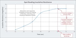
When the test voltage is first applied to the item under test, current begins to flow into the conductor. Some electrons will be absorbed into the insulation — the process of dielectric absorption. This is not current leaking through the insulation. Current also flows into the equipment or wiring and builds up a capacitive charge. The combination of dielectric absorption current and capacitive charging current causes initial megohm readings to be a low value. After these absorption currents and capacitive charging currents stabilize, the leakage current through the insulation is measured. The test equipment converts the current flow to ohms of resistance. The more leakage current flow, the lower the resistance reading. Less leakage current flow indicates greater insulation resistance. Insulation resistance is measured in ohms, kilohms, megohms, or gigohms.
If it is desired to measure actual insulation resistance, then how can it be determined when only this leakage current is being measured? The answer is: Take a reading 1-min. after energizing the item under test, and use this as a standard for each measurement.
The 1-min. reading is the spot reading test. Though a small amount of dielectric absorption current and capacitive charging current may continue to flow into the circuit after 1 min., using the industry standard of 1 min. provides consistency across many separate readings on the same equipment or cable (see the Figure).
Insulation resistance changes significantly with variations in temperature and the type of insulation. Best practice is to correct readings to a standard temperature for accurate insulation resistance values.
For example, a motor with Class B insulation was shut down a short time ago, and a quick check of the winding temperature with an infrared thermometer indicates 60°C (140°F). The spot reading test on the motor indicates 5 megohms of insulation resistance at a test voltage of 500VDC. During the previous maintenance period, a spot reading value was recorded as 30 megohms, but the motor temperature was recorded as 20°C (68°F). Rightly so, you consider the sudden drop in insulation value as suspect. However, correcting this 5 megohm reading at 60°C (140°F) to a standard 20°C (68°F) gives an insulation resistance value just more than 30 megohms. Therefore, there is no immediate concern about insulation quality. Standards and vendor information provide recommended standard temperatures, necessary calculations, or easy-to-read charts for making temperature corrections.
Best practice is to record the ambient temperature, relative humidity, dew point, winding temperature, length of time out-of-service, test voltage, and the test lead and motor lead or cable connection arrangement when the test is performed. Correct for temperature as needed to ensure consistency in testing. Plot insulation values of the items tested over time, and look for abnormal downward trends. Insulation degrades over time, so a slow steady decline is not abnormal. Look for any sudden large decreases in insulation resistance, and investigate further.
Humidity is an important consideration. Obviously, any visible moisture on insulation is a red flag, and the insulation needs to be dried. Condensation occurs when the ambient temperature reaches the dew point, and moisture in the air deposits onto the insulation. Insulation can also absorb moisture that may not be visible.
Any installation of wiring is critical for the safe operation of systems. Comply with NEC Sec. 110.7, and perform an insulation check of all branch circuit and feeder wiring once installed (Photo 3).

#5 Investigate Further
If a spot reading test indicates a potential problem, further action is required. Oftentimes, simply cleaning motor windings will significantly improve megohm readings. Insulation can be dried following the manufacturer’s instructions. The dielectric absorption ratio (DAR) and the polarization index (PI) are two insulation quality tests that can be performed with an insulation resistance tester. These tests can help identify dirty insulation or insulation containing moisture. Once identified, the problems can be corrected.
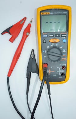
The tests are simple to perform, and, like the spot reading test, the process may require no more than pushing the appropriate labeled button on the modern insulation resistance tester. The test and calculations are performed automatically (Photo 4). The DAR test lasts for 1 min., and readings are recorded at the 30-sec and 60-sec intervals. Divide the 60-sec reading by the 30-sec reading, and the resultant number is the dielectric absorption ratio.
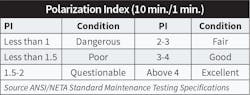
The PI test lasts for 10 min., with a measurement recorded at 1 min., then another at 10 min. Divide the 10-min. reading by the 1-min. reading, and the resultant number is the polarization index in the Table below.
In summary
Various codes, standards, and manufacturers’ instructions provide requirements and guidelines for insulation resistance testing. Following a job safety plan and written procedures is key to safe, efficient, and consistent test processes. Qualified workers must understand the theory behind insulation resistance testing and follow industry best practices to consistently obtain meaningful insulation resistance values. For both electrical contractors and facility maintenance organizations, the overall result is an industry best practice that not only minimizes downtime but also mitigates the hazards of electricity (shock and fire).
Critical Considerations for Effective Insulation Resistance Testing
-
Follow a job safety plan (LOTO), as applicable.
-
Use the proper test equipment. A multimeter does not supply sufficient voltage to conduct the test!
-
Verify integrity of all newly installed wiring per NEC 110.7
-
Correct measured values to a standard temperature.
-
Disconnect sensitive electronics to avoid damage.
-
Establish written maintenance procedures for test instructions and minimum insulation values for each type of item to be tested.
-
For the spot reading test, apply voltage for 1 min., then record resistance value.
-
Discharge insulation (especially motors) after test per test equipment instructions.
-
Ensure only qualified persons conduct tests and interpret results.
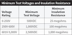
Use industry best practices for insulation voltage rating and minimum resitance:
Based on 16°C (60°F) per ANSI/NECA 91 (see Table above)
Notes:
- For rotating equipment with 600V insulation, minimum insulation resistance generally = 5 megohms
- 115V wiring minimum resitance = 2 meghoms
-
There are no consensus standards for applied test voltages and minimum insulation resistance. Use the references below for additional information.
-
ANSI/IEEE 43, Recommended Practice for Testing Insulation Resistance of Rotating Machinery
-
ANSI/NECA 91, Recommended Practice for Maintaining Electrical Equipment
-
NFPA 70B, Standard for Electrical Equipment Maintenance
-
ANSI/NETA MTS, Standard for Maintenance Testing Specifications for Electrical Power Equipment and Systems
-
Insulation resistance test equipment instructions
-
Manufacturer’s data for specific items under test
About the Author

Randy Barnett
CESCP
Randy Barnett, electrical code and safety specialist, is a master electrician, ICC commercial electrical inspector, NFPA-certified electrical safety compliance professional and has worked as an electrician and technician in nuclear and coal-fired power plants, and in industrial maintenance and construction for 40 years. He is the author of Commercial and Industrial Wiring – American Technical Publishers, numerous articles, and is seen monthly on the EC&M Tech Talk video series for EC&M magazine. Randy conducts both online and in-person classes for NTT Training where he served as program manager for over 20 years. Randy’s resources can be found at www.randybarnett.net. His email is [email protected].