Exploring Harmonics Mitigation Techniques
With the rising demand of non-linear type equipment and loads, mitigation of harmonics becomes increasingly important. If a harmonics study or testing indicates excessive harmonic levels or a potentially harmful resonance condition, then mitigation must be considered. Depending on the specific situation, several different methods can be considered for mitigating harmonics.

The Usual Suspects
Common mitigation methods include:
- Line reactors and motor drive isolation transformers use reactive harmonic attenuation effects to reduce the actual current distortion at the input terminals to the drives. Line reactors are more commonly used because of their size and cost.
- Replace 6-pulse drives with higher pulse drives, such as 12-pulse or 18-pulse versions.
- Harmonic filters can be used to mitigate problems as well. They are used in applications with a high non-linear load to overall system ratio to eliminate the harmonic currents. They can be tuned to a specific harmonic, such as 3rd, 5th, 7th, 11th, etc., to meet the requirements of the IEEE 519 standard.
- Active filters insert negative harmonics into the network, thereby eliminating the undesirable harmonic on the network.
- Passive filters are a combination of capacitors, inductors (or reactors), and resistors. They are the most common and are available for all voltage levels.
Overall, it is important to understand how the various system components interact with each other and with the power system. It’s essential that a coordinated solution be provided that meets total harmonic distortion (THD) levels, system performance demands, and power system requirements. Correcting a harmonic distortion problem in the field after installation can be very challenging, time consuming, and expensive.
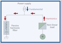
Passive filters consist of one or more tuned inductor/capacitor legs, which shunt specific harmonic currents away from the power system (Fig. 1 on page 14). They also offer the added benefit of supplying leading reactive power and thus provide power factor (PF) correction.
Figure 2 on page 14 shows a diagram of an active filter front end with an LCL filter. The active filter line inverter removes low frequencies less than 1kHz. The LCL filter, which is a passive filter, removes high frequencies greater than 1kHz. The LCL filter is inserted between the rectifier and 3-phase power supply to attenuate pulse-width modulation harmonics so that proper voltage and current THD levels are obtained.

For this setup, no transformer is required, and performance is not affected by line imbalance.
A parallel active filter is an option to help mitigate harmonics. It works by sampling the distorted current and uses fast-acting transistors to generate harmonic currents and inject them 180° out of phase.
The pros of using these filters include:
- They are sized to the harmonic content only.
- They maintain good performance at light loads.
The cons of using these filters are:
- They are expensive.
- They are susceptible to background voltage THD and imbalance.
- The complexity requires start-up and regular service by manufacturer.
A Different Choice
Another option to help mitigate harmonics is to use a variable-frequency drive (VFD) with an active front end, also known as an “active rectifier.” The 6-pulse diode bridge rectifier is replaced by a fully controlled transistor bridge.
The pros of using this device are:
- It ideally achieves lowest current THD.
- It can provide regenerative braking.
The cons of using this device include:
- It’s expensive.
- It can introduce higher order harmonics.
- It can result in higher electromagnetic radiation.
- The complexity requires start-up and regular service by manufacturer.

The Table above shows comparisons of the effectiveness of different types of harmonics mitigation methods. As you can see, no mitigation can typically result in a 72% current total harmonic distortion. The percent harmonic reduction is based on the current total harmonic distortion for a given method as compared to no mitigation at all. Going down the list, you can see how different methods are more effective than others.
Downey is a principal engineer for Western Electrical Services, Inc. He is an active member of the IEEE 1584 Working Group – Guide for Performing Arc-Flash Hazard Calculations and IEEE 1814 Working Group – Recommended Practice for Electrical System Design Techniques to Improve Electrical Safety. He can be reached at [email protected].
About the Author
Ryan Downey, P.E.
Downey is a principal engineer for AVO Training Institute (www.avotraining.com). He is an active member of the IEEE 1584 Working Group – Guide for Performing Arc-Flash Hazard Calculations and IEEE 1814 Working Group – Recommended Practice for Electrical System Design Techniques to Improve Electrical Safety. He can be reached at [email protected].