How To Make Proper Grounding and Bonding Connections
Despite plenty of EC&M resources on grounding and bonding, including theory and specific rules on the topic, the simple question we continually get from electrical professionals in the field is: “So how do I have to ground and bond?” The National Electrical Code (NEC) lists eight specific methods to make grounding and bonding connections in Sec. 250.8. Failure to install these connections properly can result in shock, fire, or, most certainly, power quality problems. Let’s take a look at each one in more detail.
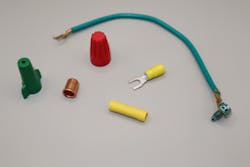
Method 1 — pressure connectors
Listed pressure connectors are the first item appearing in this list. Many of these connectors are commonly used for making bonding connections. For example, twist-on wire connectors (e.g., Wire Nuts™), often used to splice equipment grounding conductors (EGCs) fall into this category (Photo 1).
Listed pressure connectors are evaluated according to one of three UL 486 standards, such as UL486C Splicing Wire Connectors. Also included in this category are commonly used tool-crimped connectors, insulation-piercing or displacement connectors, spring-action connectors, tool-applied crimp connectors, and mechanical set-screw connectors.
With twist-on connectors, the tapered and coiled metal insert inside of an insulated plastic cap twists the conductors together as the worker turns the plastic cap. Certain industrial facilities do not allow the use of these twist-on connectors. Instead, they rely on tool-applied crimp connections or other mechanical connectors.
Always adhere to the instructions in the listing and labeling of the connectors. Each manufacturer identifies a combination of wire sizes and the number of wires that can be used for each size connector. This information is often provided on the container for the connectors. Color coding of connectors helps to select the correct size connector for the application. Additionally, manufacturers may have information as to whether pre-twisting of conductors is necessary (though many electrical workers will often do this using lineman pliers).
Most manufacturers recommend against pre-twisting. These twist-on connectors are listed for both stranded or solid conductors or a combination of each. When connecting stranded conductors with solid conductors, the stranded conductor should be placed slightly above the solid conductor, allowing the twisting motion to wrap the stranded conductor around the solid conductor. The general manufacturer recommendation is to continue to twist the connector until two wraps of the conductor are made around each other. Also, pay attention to the manufacturer’s strip lengths for conductors when removing insulation. No bare conductor should protrude from the open end of the connector, and no insulation is to be twisted underneath the coiled spring. Remember, manufacturer instructions are the result of extensive testing and design. As such, recognized testing laboratories evaluate these products based on the manufacturer’s application information. Failure to follow these instructions can not only be a violation of NEC Sec.110.3(B) but can also jeopardize the integrity of the grounding and bonding system. Considering the purposes and importance of proper grounding and bonding adherence to manufacturer instructions goes without question.
Questions continually arise regarding the use of the “green” colored twist-on connectors. Green twist-on connectors are not specifically listed for just bonding connections. Any suitably sized color connector can be used for splicing bonding conductors. These green-colored twist-on wire connectors with a hole in the top for insertions of a bonding jumper are not suitable for use for ungrounded or grounded conductors.
Tool-crimped connections provide excellent mechanical and electrical connection integrity. Once again, they must be applied according to manufacturers’ instructions as part of their listing. These connectors may be bare metal or have a plastic covering. The covering is not for insulation purposes, but for identification only as to AWG size for conductors to be inserted in the connector. Most only allow one conductor inserted into a barrel end. They are available for splicing conductors (butt splices) or terminations (ringed or forked). Once again, proper strip length is essential. The insulation should sit up against the open end of the barrel, and the bare conductor should slightly protrude or be visible at the opposite end of the barrel. Proper crimp tools (some listed) must be used to make the crimp over the correct area of the barrel with the correct pressure applied. Crimp-on connectors are listed for stranded conductors only — not solid conductors.
These tool-applied crimp connectors provide a secure splice or termination and will not vibrate or come loose over time. For terminations, the screw or lug used to attach the connector to the terminal must be torqued and properly maintained to ensure connection integrity over time. They are available for various AWG-size conductors and are typically color-coded by the manufacturer.
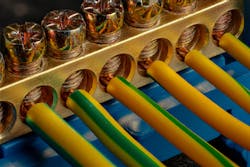
Method 2 — terminal bars
Terminal bars are often provided by equipment manufacturers to allow the connection of multiple conductors at one convenient location. Panelboards are an example where an equipment grounding bus bar is provided in the enclosure and is bonded to the enclosure. Once again, pay particular attention to instructions for installation. Unless otherwise noted in the instructions, only one conductor per terminal is allowed, and torque requirements apply (Photo 2).

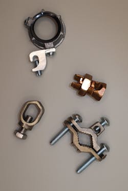
Method 3 — pressure connectors listed as grounding and bonding
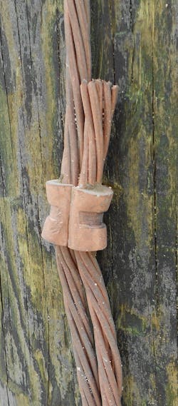
This option encompasses several distinct types of connectors. These are specifically listed for grounding and bonding applications and cannot be used in other applications unless specified. When observing the label( such as UL) the words “grounding and bonding” appear adjacent to the label. Ground clamps are identified for specified size ground rod and conductor sizes. This category also includes irreversible crimp connectors that are installed with hydraulic crimping tools (Photos 3a, b, and c).
Method 4 — exothermic welding
Exothermic welding is a chemical process that fuses conductor material to form a molecular bond. This process is permanent, and the weld is not subject to corrosion. Exothermic welding is often used for the connection of stranded copper conductors to rebar. The general rule is grounding electrode conductors must be continuous in length. However, exothermic is one method permitted to splice grounding electrode conductors.
Method 5 — machine screw-type fasteners
Machine screw-type fasteners that engage not less than two threads — or that are secured with a nut — are permitted. If a 10-32 machine screw is used in a 1/16th-in.-thick enclosure, then two of the screw threads will be engaged in the metal enclosure. Testing has shown this to be sufficient engagement for grounding and bonding purposes. If two threads cannot be engaged, then a nut can be placed on the machine screw for securement.
Machine 6 — thread-forming machine screws
Thread-forming machine screws that engage not less than two threads in the enclosure are also permitted by Sec. 250.8. Thread-forming screws displace material as they are screwed into a pilot hole. All the displaced material flows around the screw’s threads, providing a secure connection that resists loosening over time. Sheet metal and drywall screws are not permitted for grounding and bonding. Connections that use only solder are also not permitted because excessive heat in a ground fault could cause solder connections to loosen or melt.
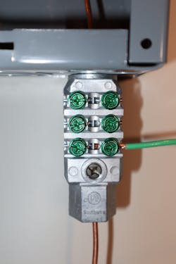
Method 7 — connections that are part of a listed assembly
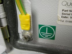
Manufacturers build control cabinets in compliance with specific standards. Panel makers will identify termination points for grounding and bonding connections. Quite often, a bonding jumper will be installed with listed pressure connectors at each end to bond the door to the enclosure (Photo 4).
Method 8 — other listed means
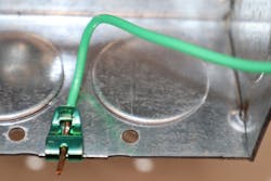
Other listed means may be considered a catch-all phrase. However, the UL Guide Information for Electrical Equipment the White Book defines these “other listed means” options. For example, ground clips used on metal boxes are listed for use on square or octagonal boxes and for solid conductors only. Other examples include grounding and bonding locknuts, grounding and bonding hubs, ground mesh used in swimming pool construction, and grounding wedge lugs (Photo 5).
How To Verify Grounding and Bonding Connections
The NEC does not specify electrical resistance values for bonding. According to the NEC, bonding must “establish electrical continuity and conductivity.” Section 250.53(A)(2) provides an exception for supplemental grounding electrode requirements: “If a single rod, pipe, or plate grounding electrode has a resistance to earth of 25 ohms or less, the supplemental electrode shall not be required.”
However, ANSI/NETA ATS-2021 Standard for Acceptance Testing Specifications for Electrical Power Equipment and Systems provides requirements. Connections require “investigation if point-to-point resistance values that exceed 0.5 ohm.” Other standards may require a maximum resistance into the earth of 5 ohms or less. Improper grounding and bonding per NEC requirements, IEEE standards and other documents are often the cause of power quality issues in distribution systems (see Sidebar below, “Five Common Errors Found in Grounding and Bonding Systems”).
Follow the Rules!
In summary, NEC Sec. 250.8 requires one of eight methods to make grounding and bonding connections. Different listed connectors are available to splice and terminate grounding and bonding conductors. Electrical workers must properly apply each of these components per manufacturers’ instructions. Knowing what connectors are available, selecting the proper connection method, having the correct tool for the job, and properly applying the connection device are critical to prevent both shock and fire hazards — and allow for proper operation of the distribution system.
Randy Barnett is the Electrical Codes Program Manager for NTT Training. He is an NFPA-certified electrical safety compliance professional with more than 40 years of industrial electrical construction, maintenance, and training experience. He has worked as a journeyman electrician in nuclear and coal-fired power plants, on railroad locomotives and in various manufacturing environments. He is the author of “Commercial and Industrial Wiring” from ATP Publishers, the EC&M Book, “Introduction to Industrial Electrical Maintenance” and numerous articles and videos, including EC&M’s popular Tech Talk video series, EC&M Asks videos, and various technical articles. Randy conducts electrical code and safety classes worldwide and holds the NCPCCI General Electrical Inspector Certificate. He can be reached at [email protected].
SIDEBAR: Five Common Errors Found in Grounding and Bonding Systems
Improper installation and maintenance of grounding and bonding systems can result in shock, fire, and power quality issues. Common errors include:
- Not applying proper torque to connections. Applying too much torque may result in a high-resistance connection.
- Use of improper connector. For example, using a tool-applied crimp connector listed for stranded conductors with a solid conductor.
- Failure to follow NEC requirements for locations to ground and bond.
- Use of improper table for sizing grounding and bonding conductors. These are the correct tables:
- Table 250.66 is for sizing the Grounding Electrode Conductor for Alternating-Current Systems
- Table 250.102(C)(1) for sizing the Grounded Conductor, Main Bonding Jumper, System Bonding Jumper, and Supply-Side Bonding Jumper for Alternating-Current Systems
- Table 250.122 for the Minimum Size Equipment Grounding Conductors for Grounding Raceway and Equipment
5. Failure to maintain grounding and bonding connections per NFPA 70B Standard for Electrical Equipment Maintenance. Compliance with this standard is now required.