Embedding electric heating elements in walkways, steps, and similar places can make these surfaces safer for winter pedestrians — but not if the installation exposes people to a shock hazard. Thus, Art. 426 provides installation requirements for fixed electrical systems that melt ice and snow from these surfaces [426.1(A)]. Article 426 also provides requirements for exposed electric melting systems on structures such as bridges, roofs, and drainage systems [426.1(B)].
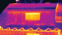
The installation requirements also help ensure reliable operation. Additional hazards may arise if one of these systems fails. Consider a roof melting system (Photo 1). Frozen material can form a dam that traps water (plus more ice and snow) on the roof. The weight of all this may collapse the roof. Similar logic applies to bridges (they need to drain), along with the need to keep them safely traversable for vehicles.
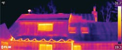
To avoid callbacks, perform functional testing when the installation is complete. But how? An efficient way is to turn the system on, and view the installation in infrared. Without this type of testing, you’d have to wait until it snows to visually verify operation (Photo 2). It’s better to fix any problems before the snowfall than be made aware of the problem after the roof collapses.
Types of systems
The NEC recognizes three types of heating systems [426.2]:
- Resistance. Part III provides the specific requirements. Current runs through a heating element embedded in, or fastened to, the surface it’s intended to heat.
- Impedance. Part IV provides the specific requirements. Current flows by direct connection to an AC voltage source from an isolating transformer through one or more pipes and/or rods, which subsequently heat up.
- Skin-effect. Part V provides the specific requirements. This type of system uses a ferromagnetic envelope embedded in, or fastened to, the surface it’s intended to heat.
A heating system isn’t just the heating element and its connection points. It includes non-heating circuit wiring, junction boxes, raceways, fittings, and other items necessary for completion [426.2]. This means Art. 426 covers much more than just what gives off heat.
Load characterization. A continuous load is one in which the maximum current is expected to continue for three hours or more [100]. Clearly, one of these systems can reasonably be expected to run longer than three hours during normal use. Consider these to be continuous loads, for purposes of your load calculations [426.4]. This means you apply the 125% rule [210.19(A)(1)].
General installation requirements
The installation requirements of Art. 110 also apply to installations covered by other Articles, except as specifically amended by those Articles. Some of these requirements never change, however.
For example, you must use only wiring methods recognized as suitable; if the wiring method isn’t in the NEC, don’t use it [110.8]. Outdoor installations seem particularly prone to inviting trouble on this issue, as has been amply documented over the years in the Illustrated Code Catastrophes column.
One general requirement that’s often repeated in specific Articles is to install equipment in a way that protects it from physical damage. Yet another iteration of this is in Art. 426 [426.11]. The NEC does not specify how to do this because there is no practical way to account for the thousands of possibilities. The expectation is you’ll use your training and experience to determine what to do [90.1].
Of course, the equipment must be identified as suitable for the installation [426.10]. But specifically, this includes the chemical, thermal, and physical environment. Also, the installation must comply with the manufacturer’s drawings and instructions; if compliance isn’t possible, the equipment isn’t suitable.
Some of this equipment can generate enough heat to burn skin. Thus, there’s a requirement to keep the external surfaces isolated from people if the system operates at 140°F or higher [426.12]. Regardless of the temperature, the presence of this equipment must be evident by clearly visible caution signs or markings [426.13].
Resistance heating
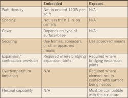
Of the three types of heating covered by Art. 426, resistance heaters have the most requirements. The requirements for heating leads vary depending upon whether the equipment is embedded or exposed [426.20 vs. 426.21] (see Table above).
Similarly, the requirements for non-heating leads vary along this same demarcation [426.22 vs. 426.23]. The installation of non-heating leads must meet five requirements [426.22(A) through (E) if for embedded equipment], but only two if exposed [426.23] (and they don’t overlap).
A situation may arise where you need to electrically connect a heating element to a non-heating element because there’s no factory connection. In this situation, use only connectors identified for the purpose [426.24(A)].
If you make splices or terminations at the ends of the non-heating leads, you must install these in a box or fitting that conforms to 110.14 and 300.15 [426.24(B)].
Part III includes a corrosion protection requirement [426.26] that is similar, but not identical, to a corrosion protection requirement in Part V [426.43]. Basically, any raceways, fittings, etc., that are in contact with the earth (or are subject to severe corrosive influences) must have suitable corrosion protection.
Parts III, IV, and V each include a different grounding requirement:
- Part III (resistance): It must have a grounding means as part of the heated section of the cable, panel, or unit [426.27].
- Part IV (impedance): If it operates between 30V (noninclusive) and 80V (inclusive), it “must be grounded at a designated point(s)” [426.34]
- Part V (skin-effect): Connect the ferromagnetic envelope to an equipment grounding conductor at each end [426.44].
Part III ends with a requirement that’s worded as if it’s a general requirement for all three types of this equipment: provide ground fault protection [426.28]. The NEC is silent on GFCI specifically for skin-effect heating, but for impedance heating imposes additional requirements if GFCI isn’t provided for the secondary winding of the transformer [426.32].
The NEC is silent on what to do if loss of power due to GFCI operation would introduce hazards the system was intended to prevent. For many applications, it’s smart to consult the manufacturer about alarm options.
Impedance heating
In addition to requirements we’ve already covered, impedance heating systems must use an isolation transformer (with grounded shield between the secondary and primary windings) to isolate the distribution system from the heating system [426.31].
Induced current is a concern, so you must follow the requirements for ferrous metal enclosures and raceways [426.33]. The main idea is you group all phase conductors together, along with (if you use it) the grounded conductor (at this voltage, it’s the neutral) and all equipment grounding conductors [300.20(A)].
If you run a single conductor, the slotting requirement of 300.20(B) applies (also true for skin-effect systems). Alternative to slotting, you can run all of the conductors of the circuit through an insulating wall of sufficient size.
Skin-effect
In addition to the requirements we’ve already covered:
- Pullboxes, where used, must be accessible without excavation (put them above grade or in suitable vaults) [426.41].
- Outdoor pullboxes must be water-tight.
Disconnects
You must provide a means to disconnect this equipment from its ungrounded conductors (and they must disconnect simultaneously). Any disconnect you use must be:
- Of the indicating type.
- Capable of being locked open [426.50(A)].
Either of these can serve as the disconnect:
- The branch circuit switch or circuit breaker, if readily accessible to the user [426.50(A)].
- The factory-installed attachment plug of cord- and plug-connected equipment, if rated 20A or less and 150V or less (to ground) [426.50(B)].
Any cord- and plug-connected equipment must be listed [426.54]. If both intended for and identified for this use, you must install it per Article 422 [426.3].
Controllers
The requirements for temperature controllers vary, depending upon the type [426.51]:
- With “OFF” position. If the controlled switching device has an “OFF” position that interrupts the current, it must open all ungrounded conductors when in that position. It can serve as the disconnect only if lockable per 110.25.
- Without “OFF” position. It doesn’t have to open all ungrounded conductors, but you can’t use it as a disconnect.
- Remote. In practical terms, same as with no “OFF” position.
Then there are combined switching devices. These are switching devices consisting of combined temperature-actuated devices and manually controlled switches that serve as both the controller and disconnect [426.51(D)]. They must:
- Open all ungrounded conductors when manually placed in the “Off” position.
- Prevent circuit energization while in the “Off” position.
- Be lockable per 110.25.
None like it hot
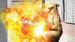
The NEC does a good job of anticipating likely hazards and providing requirements to protect against them. But those serving on the Code Making Panels can’t possibly imagine every scenario. Even if Art. 426 doesn’t explicitly require some preventive measure, the need to protect innocent people might.
You can “meet Code” yet leave the seeds of a shock hazard. So examine the application for possible issues and design potential hazards out before installing the equipment. For example, your intended raceway path poses no physical damage threats during normal operations. But during the annual shutdown, it would. Choosing a longer route along the other side of the building just may save someone’s life.
Lamendola is an electrical consultant located in Merriam, Kan. He can be reached at [email protected].
