Harmonics: What Electrical Contractors Need to Know — Part 2
Key Takeaways
- Harmonics are a form of power pollution that can cause overheating, nuisance trips, and equipment failure, making their identification and mitigation critical for system reliability.
- Standards like IEEE 519 and IEC 61000-4-7 define measurement methods and compliance limits, ensuring consistent and reliable harmonic analysis across different regions.
- Effective harmonic measurement requires specialized analyzers that can break down waveforms into individual frequency components, beyond simple THD readings.
- Parameters such as THD, individual harmonic orders, crest factor, and K-factor provide detailed insights into harmonic sources and their impact on equipment and transformers.
- Mitigation strategies include passive filters, active harmonic filters, line reactors, chokes, and phase-shifting transformers, each suited to specific system conditions and harmonic profiles.
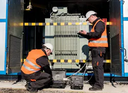
In Part 1 of this series, we defined harmonics as "power pollution" that can cause unexplained overheating, nuisance trips, and equipment failure in electrical systems. We pointed out that the challenge for electrical contractors lies in identifying harmonics and assessing when they reach a critical threshold for action. In this article, we move from theory to application: how to measure these distortions, the standards that govern them, and the methods used to bring a system back into balance.
Industry standards for harmonics
Harmonic issues are rarely solved by looking at one number. A high THD value may tell you distortion is present, for instance, but it won’t tell you why it’s happening or what mitigation method to use. That’s where standards, proper measurement methods, and a basic understanding of harmonics come together.
Here are the key things to know about the standards: IEEE 519 is primarily applied in North America, and IEC 61000-4-7 is used in Europe and other parts of the world. These two harmonic standards use the same core measurement techniques, but they are applied differently.
Like any measurement, harmonic measurements need to be appropriate and repeatable. If two qualified meters are measuring the same circuit at the same time, the results should be comparable. Without recognized measurement methods, harmonic readings can be unreliable and cannot be defended.
IEC 61000-4-7 was the first standard to define harmonic measurement methods and is the basis of IEEE 519 described below. It defines the measurement techniques for voltage and current harmonics and interharmonics in 50 Hz and 60 Hz systems. Harmonics are integer multiples of the fundamental frequency (i.e., 120 Hz, 180 Hz, etc.), while interharmonics are frequencies in between the integer harmonics.
IEC 61000-4-7 defines harmonic parameters and measurement methods, but not harmonic compliance limits, which are defined in other IEC standards. Measurements are made on a 200-millisecond measurement window that equals 12 cycles on a 60 Hz system or 10 cycles on a 50 Hz system. This timing detail may sound academic, but it has practical value. Harmonic distortion can change quickly as equipment cycles on and off, production lines start and stop, or drives change speed. A standards-based measurement method gives the data a consistent foundation.
IEEE 519 is primarily applied in North America. Starting with the 2014 revision, and updated in 2022, IEEE 519 uses the measurement methods of IEC 61000-4-7 but adds two parameters and compliance limits. Very short time and short time harmonics are 3-second and 10-minute aggregations respectively of individual harmonics. These two new parameters are the basis of daily and weekly pass/fail compliance limits at different voltage and current levels.
Note that IEEE 519 is intended for use at the point of common coupling (PCC), which is usually the interface between the utility and the user. For contractors, it’s important to remember that IEEE 519 is generally used to evaluate how a facility impacts the utility grid, rather than assessing every individual branch circuit.
How are harmonics measured?
Effective troubleshooting for suspected harmonics requires more than a standard multimeter. A power quality analyzer that complies with the above standards reliably breaks down a distorted waveform into its individual frequency components for analysis.
Remember that most harmonics originate in the current draw of non-linear loads. Generators produce fairly “clean” power that is distorted by the loads we plug into them. Current harmonics can then distort the voltage across the impedance of the power system. This voltage distortion can then affect the entire system. Most power quality meters report harmonic information in several ways, as explained below.
Total harmonic distortion
Total harmonic distortion, or THD, is often the first number people look at. It gives one percentage value for the combined harmonic content relative to the 50 Hz or 60 Hz fundamental frequency. Most PQ meters report both voltage THD and current THD.
THD is a good screening value. It tells you whether distortion is present and whether it may deserve more attention. But it doesn’t tell the full story. Looking at the individual harmonic content can indicate where the harmonics originated, their effects on the power system, and possible mitigation methods if necessary.
For example, a system with a high 5th harmonic may call for a different correction approach than a system with high 3rd or triplen harmonic content. Both may produce an elevated THD value, but the cause and correction may be different. That is why THD should be treated as the starting point, not the diagnosis.
Individual harmonic orders
A harmonic spectrum shows each harmonic order (multiple of the fundamental) and its magnitude and phase. Instead of giving one combined distortion value, it shows the levels of the 3rd, 5th, 7th, 9th, 11th, and other harmonic orders. Odd harmonics are mostly seen in our power systems, but even order harmonics can occur in certain situations. This is where troubleshooting becomes more useful.
A large 3rd harmonic may point toward neutral heating concerns in systems with many nonlinear loads; 5th or 7th harmonics may be associated with other types of loads, such as VFDs.
Crest factor
Crest factor compares the peak value of a waveform to its RMS value. This is useful because some nonlinear loads draw current in sharp pulses. The RMS current may not look excessive, but the waveform may still have high peaks that stress equipment.
A higher crest factor can be a sign that the load current is peaky. This is good to know when evaluating electronic loads, UPS systems, power supplies, and circuits with pulsed current draw.
Crest factor does not replace harmonic analysis, but it can give useful context when equipment appears to be under more stress than the RMS current suggests.
K-factor
K-factor is used when evaluating transformer heating from harmonic currents. Higher-order harmonic currents can create added heating in transformer windings. K-factor weighs harmonic currents based on their order, helping determine whether a transformer is properly rated for the loads it serves.
This is especially relevant in buildings or facilities with a high concentration of nonlinear loads, such as data centers, commercial buildings with dense computer, LED and other electronic loads, and industrial sites with drives and rectifiers.
A transformer may be correctly sized for kVA and still be poorly matched to the harmonic profile of the load. K-factor helps address that issue.
Strategies for harmonic mitigation
Understanding and mitigating harmonics can be a specialized field, so make sure that your team has the appropriate skill set.
Before adding filters, replacing equipment, changing transformer ratings, or redesigning part of the distribution system, the contractor or engineer needs to understand which harmonic orders are present, where they are coming from, and whether the distortion is constant or tied to a specific operating condition. Possible interactions with the system impedance should also be reviewed when considering various mitigation methods. Below are some possible mitigation options.
Passive filters
Passive filters are tuned to absorb specific harmonic frequencies. They are often applied when one or more known harmonic orders are creating problems.
They can work well in certain applications, where the load profile is stable and the harmonic order is known. But they need to be selected with care. A poorly applied passive filter can interact with capacitors, transformers, or system impedance and create resonance.
Passive filters are usually a better fit when the harmonic issue is well understood and the system does not change much from hour to hour.
Active harmonic filters (AHF)
Think of these as "noise-canceling headphones" for the power system. They monitor the waveform in real time and inject a counteracting current to cancel out the distortion.
They are often useful where load conditions change throughout the day. This may include facilities with variable production loads, multiple drives, chargers, rectifiers, or a changing mix of nonlinear equipment.
An active filter may be considered when several harmonic orders are present or when the load profile changes by shift, process, or operating mode.
Line reactors and chokes
These are simple, cost-effective inductors installed at the source (such as a VFD). They limit the rate of current change, smoothing out the "pulses" and reducing harmonic generation at the source, especially with drives, rectifiers, inverters, and other power electronic loads.
They may also help reduce some electrical stress at equipment terminals, depending on the application. In many cases, they are used close to the harmonic-producing equipment rather than as a system-wide correction method.
Line reactors and chokes are often considered when the goal is to reduce the distortion created by a specific piece of equipment.
Phase-shifting transformers
Phase-shifting transformers can help cancel specific harmonics in balanced three-phase systems. They do this by shifting the phase relationship between transformer outputs so certain harmonic currents offset each other.
This approach is often considered when harmonic-producing loads can be grouped and served in a planned way. It is not a quick fix for every site, but it can be useful during new construction, distribution redesign, or major equipment upgrades.
The system needs to be evaluated carefully, since phase-shifting methods depend on load balance and how the nonlinear loads are arranged.
Key takeaways
IEEE 519 helps evaluate harmonic limits at the PCC. IEC 61000-4-7 defines how harmonics and interharmonics are measured up to 9 kHz.
Harmonic mitigation is not a one-size-fits-all solution. A strategy that works for a data center might be entirely wrong for a wastewater treatment plant.
If harmonics are suspected, the best approach is to avoid guessing. Measure the harmonic profile, identify the dominant harmonic orders, understand where the distortion is coming from, and then choose the correction method that fits the actual problem. By matching the mitigation method to the actual data, you ensure the system remains compliant, efficient, and, most importantly, operational.
About the Author
 Ross Ignall
Ross Ignall
Ross Ignall is the Director of Business Development and Marketing at Dranetz Technologies, a GMC Instruments company, where he has more than two decades of experience in power monitoring and analysis. With a background in engineering and product management and a career focused on instrumentation, power quality and energy solutions, Ross has been instrumental in building the GMC Instruments brand Dranetz. He works closely with engineers, utilities, and facility teams to align technology with real-world needs. A published author, IEEE and IEC committee member, and speaker in the fields of instrumentation, power quality, and demand/energy, he is a trusted resource in helping organizations take a smarter, data-driven approach to power system reliability. Ross can be reached at [email protected].