The National Electrical Code (NEC) requires a given conductor to be a minimum size for a given load under specific conditions of use. The reason for this is to protect the conductor insulation from overheating. So, to understand conductor sizing, you need to understand a little about conductor insulation.
Table 310.104(A) provides information on conductor insulation properties, such as letter type, operation temperature, application, insulation, and outer cover properties. Only conductors in Tables 310.104(A) though 310.104(E) can be installed, and a given conductor can be used for only the application(s) the tables identify it for.
In general, you can use only conductors contained in Tables 310.104(A), except where otherwise permitted in the NEC (an example being PV wire [690.31(C)]).
It’s common to see conductors with a dual insulation rating, such as THHN/THWN. You can use this type of conductor in a dry location at the THHN 90°C ampacity. If you use it in a wet location, you must adhere to the THWN ampacity rating of the 75°C column of Table 310.15(B)(16) for THWN insulation types. When the insulation type has the suffix “-2”, you can use the conductor in a wet or dry location at the 90°C ampacity rating. THWN-2 is an example.
Conductor Sizes
Conductor sizes are expressed in American Wire Gauge (AWG), typically from 18 AWG up to 4/0 AWG. Conductor sizes larger than 4/0 AWG are expressed in kcmil (thousand circular mils) [Sec. 110.6].
There’s a misconception that 12 AWG copper is the smallest conductor permitted for commercial or industrial facilities. Although this isn’t true based on NEC rules, it may be a local code requirement or otherwise specified for the project.
The smallest conductor permitted for branch circuits for residential, commercial, and industrial locations is 14 AWG copper, except as permitted elsewhere in the NEC [Sec. 310.106].
Attend One of EC&M’s Upcoming Code Change Conferences Taught by Mike Holt:
St. Louis 2020 Code Change Conference | October 29-30, 2019
Philadelphia 2020 Code Change Conference | November 12-13, 2019
Seattle 2020 Code Change Conference | December 11-12, 2019
Boston 2020 Code Change Conference | January 28-29, 2020
Massachusetts Amendments Session | January 28, 2020 (evening)
You can use conductors smaller than 14 AWG for:
• Class 1 remote-control circuits [Sec. 725.43].
• Fixture wire [Sec. 402.6].
• Motor control circuits [Table 430.72(B)].
Conductors 8 AWG and larger must be stranded when installed in a raceway unless specifically permitted elsewhere [Sec. 310.106(C)]. Solid conductors are often used for the grounding electrode conductor [Sec. 250.62] and for bonding pools, spas, and outdoor hot tubs [Sec. 680.26(C)].
You must size conductors using their ampacity from the insulation temperature rating column of Table 310.15(B)(16) that corresponds to the lowest temperature rating of any terminal, device, or conductor of the circuit.
For motors marked with design letters B, C, or D, you can use conductors having an insulation rating of 75°C or higher if the ampacity of such conductors doesn’t exceed the 75°C ampacity listed in Table 310.15(B)(16) [110.14(C)(1)(a)(4)].
For equipment rated 100A or less, you must size the conductors using the 60°C temperature column of Table 310.15(B)(16) [110.14(C)(1)(a)(2)].
Where you have terminals for equipment rated over 100A and/or pressure connector terminals for conductors larger than 1 AWG, you must size the conductor per the 75°C temperature rating listed in Table 310.15(B)(16) [110.14(C)(1)(b)(1)].
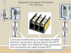
Fig. 1. It’s important to know the temperature rating of your pressure connectors when sizing your conductors.
Conductors rated 90°C and that terminate on separately installed pressure connectors can be sized to the 90°C column of Table 310.15(B)(16) if the conductors and pressure connectors are rated at least 90°C [110.14(C)(2)] (Fig. 1).
Overcurrent Protection
Conductor sizing and overcurrent protection sizing go hand in hand, so let’s look briefly at overcurrent protection.
Article 240 covers the general requirements for overcurrent protection and the installation requirements of overcurrent protection devices (OCPDs). Overcurrent is a condition where the current exceeds the rating of equipment or ampacity of a conductor due to overload, short circuit, or ground fault [Art. 100].
An OCPD protects the circuit by opening when the current reaches a value that will cause an excessive or dangerous temperature rise (overheating) in the protected conductor(s). OCPDs must have an interrupting rating sufficient for the maximum possible fault current available on the line-side terminals of the equipment [Sec. 110.9]. Electrical equipment must have a short-circuit current rating (SCCR) that permits the circuit’s OCPD to clear short circuits or ground faults without extensive damage to the circuit’s electrical components [Sec. 110.10 Note].
There are many different rules for protecting conductors and equipment. It’s not simply using 12 AWG wire and a 20A breaker. The general rule is that conductors must be protected at the point where they receive their supply per their ampacities, as listed in Table 310.15(B)(16) [Sec. 240.21].
Except as permitted by Sec. 240.4(A) through (G), conductors must be protected against overcurrent per their ampacity after ampacity correction and adjustment required in Sec. 310.15.
For OCPDs rated 800A or less [Sec. 240.4(B)], the next higher standard rating of OCPD listed in Sec. 240.6(A) (above the ampacity of the ungrounded conductors being protected) is permitted. But only if all the following conditions are met:
(1) The conductors aren’t part of a branch circuit supplying more than one receptacle for cord- and plug-connected loads.
(2) The ampacity of a conductor, after the application of ambient temperature correction [Sec. 310.15(B)(2)(a)], conductor bundling adjustment [Sec. 310.15(B)(3)(a)], or both, doesn’t correspond with the standard rating of a fuse or circuit breaker in Sec. 240.6(A).
(3) The next higher standard OCPD rating from Sec. 240.6(A) doesn’t exceed 800A.
Let’s run through some example problems to drive these points home.
Example No. 1
What’s the maximum size OCPD that can be used to protect 1 AWG conductors, where each conductor has an ampacity of 130A at 75°C, per Table 310.15(B)(16), and the calculated load is 104A?
A quick check of the Table reveals the answer to be 150A [Sec. 240.6(A)].
Example No. 2
What’s the maximum size OCPD that can be used to protect 500kcmil conductors, where each conductor has an ampacity of 380A at 75°C, per Table 310.15(B)(16), and the calculated load is 370A?
A quick check of the Table reveals the answer to be 400A [Sec. 240.6(A)].
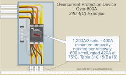
If the circuit’s OCPD exceeds 800A, the conductor ampacity must have a rating of not less than the rating of the OCPD [Sec. 240.4(C)]. But that’s only after the application of ambient temperature correction [Sec. 310.15(B)(2)(a)], conductor bundling adjustment [Sec. 310.15(B)(3)(a)], or both.
See if you can answer this question.
What’s the minimum size 75°C conductors allowed to be protected by a 1,200A OCPD using three sets of conductors per phase (Fig. 2)?
Fig. 2. If the circuit’s overcurrent device exceeds 800A, the conductor must have an ampacity not less than the overcurrent device rating.
You first need to determine the conductor ampacity per raceway:
1,200A ÷ 3 = 400A
A quick check of Table 310.15(B)(16) shows a 600kcmil conductor is rated for 420A at 75°C.
Total conductor ampacity = 420A × 3 conductors = 1,260A
Small Conductors
Unless specifically permitted in Sec. 240.4(E) or (G), overcurrent protection must not exceed the following [240.4(D)]:
(1) 18 AWG Copper, 7A
(2) 16 AWG Copper,10A
(3) 14 AWG Copper, 15A
(4) 12 AWG Aluminum/Copper-Clad Aluminum, 15A
(5) 12 AWG Copper, 20A
(6) 10 AWG Aluminum/Copper-Clad Aluminum, 25A
(7) 10 AWG Copper, 30A
What about transformer secondary conductors? The primary OCPD sized per Sec. 450.3(B) is considered suitable to protect the secondary conductors of a 2-wire (single-voltage) system — but only if the primary OCPD doesn’t exceed the value determined by multiplying the secondary conductor ampacity by the secondary-to-primary transformer voltage ratio [Sec. 240.4(F)].
Overcurrent Protection for Specific Applications
Overcurrent protection for specific equipment and conductors must comply with the requirements referenced in Table 240.3.
Air-conditioning and refrigeration equipment, and their circuit conductors, must be protected against overcurrent per Sec. 440.22. Typically, the branch-circuit ampacity and OCPD size are marked on the equipment nameplate [Sec. 440.4(A)].
Let’s look at an example problem.
What size branch-circuit OCPD is required for an air conditioner when the nameplate indicates the minimum circuit ampacity is 23A, with maximum overcurrent protection of 35A?
Answer: 10 AWG, 35A protection (See nameplate). Equipment must be installed per the manufactures instructions [Sec. 110.3(B)].
Motors and their circuit conductors must be protected against overcurrent per Art. 430 [Sec. 240.3].
Let’s run through a motor example problem now.
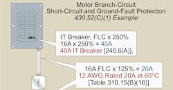
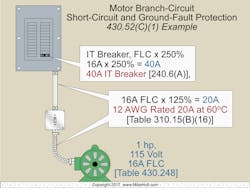
What size branch-circuit conductor and OCPD (circuit breaker) is required for a 1-hp, 115V, single-phase motor with 60°C terminals (Fig. 3)?
Fig. 3. Here’s a simple example of how to protect a motor branch circuit from short circuits and ground faults.
Answer: 12 AWG rated 20A at 60°C branch-circuit conductor with a 40A OCPD.
Now Art. 430 requirements apply [Table 240.3].
Sec. 460.6(A)(1), use motor full-load current (FLC) from appropriate tables to size conductors and OCPD. Table 430.248 gives the motor FLC for a 1-hp, 115V motor, 16 FLC.
Motor conductor size, use Sec. 430.22, 16 FLC × 125% = 20A, Table 310.15(B)(16), 12 AWG rated 20A at 60°C [110.14(C)(1)(a)(1)].
Motor OCPD size, use Sec. 430.52(C), circuit breaker uses 250% of FLC, 16 FLC × 250% = 40A which is a standard size [240.6(A)].
Getting it Right
Factors that affect conductor sizing include conductor ampacity, equipment terminal temperature rating, continuous load factors, overcurrent current protection requirements, conductor insulation temperature rating, ambient temperature conductor ampacity correction, and conductor bundle conductor ampacity adjustment.
You must account for all these to arrive at the minimum safe size for a given conductor. You may want to exceed that size after considering factors such as voltage drop, to optimize performance. However, you can never go below that size.
If you’re sizing the conductors for a given system, you are probably also sizing the overcurrent protection, so you need to understand both to do the job right.
These materials are provided to us by Mike Holt Enterprises of Leesburg, Fla. To view additional Code training materials offered by this company, visit www.mikeholt.com.
About the Author

Mike Holt
Mike Holt is the owner of Mike Holt Enterprises (www.MikeHolt.com), one of the largest electrical publishers in the United States. He earned a master's degree in the Business Administration Program (MBA) from the University of Miami. He earned his reputation as a National Electrical Code (NEC) expert by working his way up through the electrical trade. Formally a construction editor for two different trade publications, Mike started his career as an apprentice electrician and eventually became a master electrician, an electrical inspector, a contractor, and an educator. Mike has taught more than 1,000 classes on 30 different electrical-related subjects — ranging from alarm installations to exam preparation and voltage drop calculations. He continues to produce seminars, videos, books, and online training for the trade as well as contribute monthly Code content to EC&M magazine.


